8 Adjustments
8.6.3 Setting the Speed Bias
8-28
8.6.3 Setting the Speed Bias
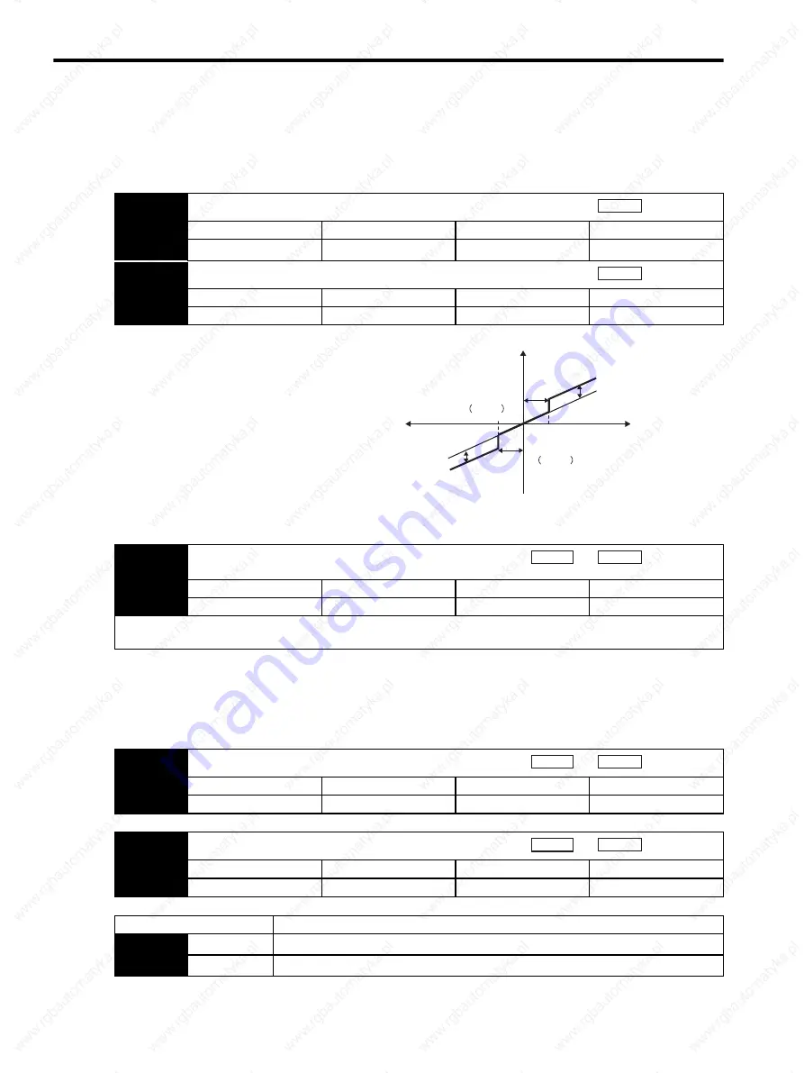
The settling time for positioning can be reduced by setting the following parameters to add bias in the speed
reference block in the SERVOPACK.
8.6.4
Speed Feedback Filter Time Constant
8.6.5 Speed Feedback Compensation
The speed feedback compensation can be used to reduce vibration and allow a higher speed loop gain to be set. In
the end, the speed feedback compensation allows the positioning settling time to be reduced because the position
loop gain can also be increased if the speed loop gain can be increased.
Pn107
Bias
Setting Range
Setting Unit
Factory Setting
Setting Validation
0 to 450 RPM
1 RPM
0 RPM
Immediately
Pn108
Bias Addition Width
Setting Range
Setting Unit
Factory Setting
Setting Validation
0 to 250 units
1 Reference units
7 units
Immediately
Position
Position
To reduce the positioning time, set these parameters
based on the machine’s characteristics.
The Bias Addition Width (Pn108) specifies when the
Bias (Pn107) is added and the width is expressed in
position error pulse units. The bias input will be
added when the position error pulse value exceeds
the width set in Pn108.
Bias addition width
Bias set
Bias (Pn107)
Bias (Pn107)
No bias
Pn108
Bias addition width
Pn108
Pn108
Position error pulse
Speed reference
Pn308
Speed Feedback Filter Time Constant
Setting Range
Setting Unit
Factory Setting
Setting Validation
0.00 to 655.35 ms
0.01ms
0.00ms
Immediately
Sets the 1st-order filter for the speed loop’s speed feedback. Makes the motor speed smoother and reduces vibration. If the
set value is too high, it will introduce a delay in the loop and cause poor responsiveness.
Speed
Position
Pn110
Online Autotuning Method
Setting Range
Setting Unit
Factory Setting
Setting Validation
−
−
0012
After restart
Speed
Position
Pn111
Speed Feedback Compensation
Setting Range
Setting Unit
Factory Setting
Setting Validation
1% to 500%
1%
100%
Immediately
Speed
Position
Parameter
Function
Pn110
n.
0
Speed feedback compensation is used.
n.
1
Speed feedback compensation is not used. (Standard speed feedback)
Содержание SGDS Sigma III Series
Страница 3: ...SGDS Sigma III Servo Amplifier User Manual for Mechatrolink II Communications...
Страница 21: ......
Страница 29: ...1 Outline 1 8 2 Connecting to SGMSH SGMGH Servomotors Power Supply Three phase 200VAC SGMGH Servomotor...
Страница 59: ...2 System Selection 2 5 4 Regenerative Resistors 2 28...
Страница 68: ...3 3 SERVOPACK Internal Block Diagrams 3 9 3 3 3 Three phase 200 V 1 0 kW...
Страница 82: ...3 7 Dimensional Drawings of Base mounted SERVOPACK Model SGDS 12A 12A 3 23 Three phase 1 5kW...
Страница 133: ...5 Wiring 5 7 2 Connecting Externally Regenerative Resistors 5 28...
Страница 229: ...7 Operation 7 7 4 Absolute Encoder Home Position Offset 7 38...
Страница 375: ...Sigma II User s Manual Index Index 8...


