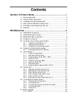
Contents
Cautions To Ensure Safety ............................................................1
1-1 Basic safety points ............................................................................. 2
1-2 System design safety points .............................................................. 2
1-3 Installation and wiring safety points ................................................... 3
1-4 Start-up and maintenance safety points ............................................. 4
1-5 Precautions when disposing of the unit .............................................. 4
1-6 Warranty ............................................................................................. 4
PROFIBUS Unit...............................................................................5
2-1 PROFIBUS unit features .................................................................... 6
2-2 PROFIBUS system concept ............................................................... 7
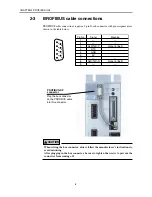
2-3 BROFIBUS cable connections ........................................................... 8
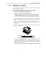
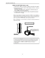
2-4 Parallel I/O connector ......................................................................... 9
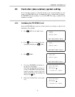
2-5 Controller (slave station) system setting .......................................... 11
2-5-1
Validating the PROFIBUS unit ..................................................... 11
2-5-2
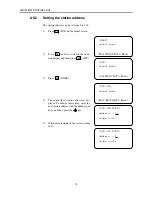
Setting the station address ........................................................... 12
2-5-3
Checking the communication speed ............................................ 13
2-6 Sequencer (master station) settings ................................................ 14
2-6-1
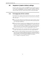
Exchanging data with the controller ............................................. 14
2-7 I/O information .................................................................................. 15
2-7-1
Profile (I/O signal table) ................................................................ 15
2-7-2
Dedicated command inputs .......................................................... 17
2-7-3
General-purpose inputs (SI200 - SI231) ...................................... 21
2-7-4
Interlock (LOCK) .......................................................................... 22
2-7-5
Emergency stop input (EMG) ....................................................... 22
2-7-6
Service mode (SVCE) .................................................................. 23
2-7-7
Dedicated outputs ........................................................................ 24
2-7-8
General-purpose outputs (SO200 - SO231) ................................ 25
2-8 Timing chart...................................................................................... 26
2-8-1
Right after controller power turns on ............................................ 26
2-8-2
Dedicated input command execution ........................................... 27
2-8-3
When interlock signal is input ....................................................... 31
2-8-4
When emergency stop signal is input .......................................... 32
2-8-5
When an alarm is issued .............................................................. 33
2-8-6
When point movement commands are run .................................. 34
2-9 I/O assignment change function ....................................................... 35
2-9-1
Changing the I/O assignment ....................................................... 35
2-9-2
I/O assignment list ........................................................................ 36
2-9-3
I/O assignment selection parameter description .......................... 38
2-9-4
I/O signal descripion ..................................................................... 40
2-9-5
Timing chart ................................................................................. 45
2-10 Robot language ................................................................................ 55
2-10-1
MOVF ........................................................................................... 55

