10
CHAPTER2 PROFIBUS Unit
■
When the SRCP/SRCD series is used:
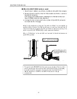
1. Short Pin No. 1 (EMG 1) and Pin No. 2 (EMG 2) of the EXT.CN connector.
2. Short Pin No. B-4 (LOCK) of the I/O.CN connector and Pin No. 4 (24G) of
the EXT.CN connector.
(This wiring can be eliminated by disabling bit 6 (Interlock function set-
ting) of PRM34 (System mode selection).)
3. Connect Pin No. 3 (24V) and Pin No. 4 (24G) of the EXT.CN connector
to an external 24 volt supply.
If Step 1 is not completed, an emergency stop will occur. If Step 2 is not completed, an
interlock will be activated. The robot cannot move in either case. Also note that 24
volt power will not be supplied to the I/O circuit unless connected as in Step 3. An
alarm is issued (06:24V POWER OFF) and the operation is disabled.
Refer to “I/O Interface” in the controller user's manual for detailed information on
parallel I/O operation.
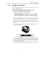
A20
A19
•
•
•
•
•
•
•
•
•
•
•
A3
A2
A1
B20
B19
•
•
•
•
•
•
•
•
•
•
•
B3
B2
B1
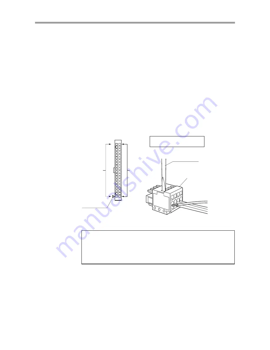
Triangular mark
(on side of connector)
12
34
Slotted screwdriver
Terminal numbers are not actually
indicated, but designated from 1 to
4, from the left as viewed from the
front (wire insertion side) as shown
in the drawing.
←
Left:
I/O.CN connector pin layout
↓
Below: EXT.CN connector pin layout
The register in the PROFIBUS unit has an emergency stop input. However, this is
just for control by the software and is not by itself totally adequate. So installing
an interlock circuit for emergency stop using the above mentioned Pin No.1
(EMG1) and Pin No. 2 (EMG2) of the EXT.CN connector is strongly
recommended.


