background image

38

CHAPTER2  PROFIBUS Unit

2-9-3

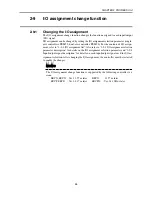
I/O assignment selection parameter description

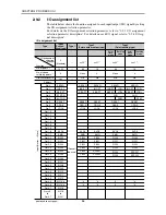
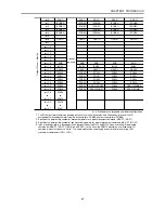
The I/O assignment selection parameter (single-axis controllers: PRM59, dual-axis con-
trollers: PRM26) selects the function to be assigned to each I/O signal.
This parameter setting allows changing the function assigned to each I/O signal. This
makes it possible to output the destination point number and perform jog movement.
After changing the I/O assignment, the controller must be restarted to enable the changes.

M E M O

M E M O

The I/O assignment selection parameter is supported by the following controller ver-
sions:

ERCX, SRCX : Ver. 13.57 or later

DRCX

: Ver. 18.57 or later

SRCP, SRCD

: Ver. 24.17 or later

SRCP30

: Ver. 24.30H or later

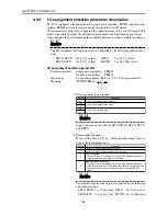
I/O assignment selection parameter

Parameter number

Single-axis controllers : PRM59
Dual-axis controllers

: PRM26

Input range

0 or another number (Refer to "2-9-2 I/O assignment list".)

Meaning

PRM59/PRM26 = x  x   xx

↑ ↑ ↑

e w q

q

 I/O assignment type selection

00

20

21

30

31

Description

Value

Type 0 (Conventional type/standard)

Type 2 (Point number output type)

Type 3 (Point teaching type)

M E M O

M E M O

Type 1 cannot be used with the SRCP, SRCD, SRCX, SRCX,
and DRCX.

w

 Point output selection

Make setting only for Type 2 (Point number output type) or
Type 3 (Point teaching type).

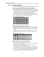
0

1

2

3

Description

Value

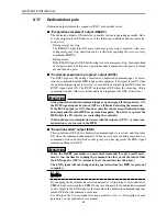
Outputs PO when movement ends normally.

Outputs PO when movement command is received.

Point zone output

Outputs PO when the robot enters the 

±

 position judgment parameter 

range for point data registered in the controller.

Movement point zone output 

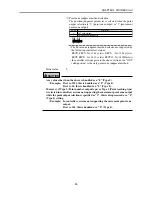
Outputs PO when the robot enters the 

±

 position judgment parameter 

range for point data that is registered in the controller and serves as the 
movement target position of a point movement command (ABS-PT, 
INC-PT).

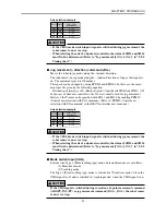
M E M O

M E M O

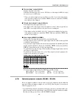
The movement point zone output is supported by the following
controller versions:

ERCX, SRCX : Ver. 13.64 or later DRCX : Ver. 18.64 or later
SRCP, SRCD : Ver. 24.21 or later SRCP30 : Ver. 24.30H or later

Содержание SRCD

Страница 1: ...al ENGLISH E IM Operations 882 Soude Naka ku Hamamatsu Shizuoka 435 0054 Japan URL http www yamaha motor jp robot index html YAMAHA MOTOR CO LTD YAMAHA NETWORK BOARD SRCD SRCP ERCX SRCX DRCX PROFIBUS E88 Ver 2 01 ...

Страница 2: ......

Страница 3: ...is manual only contains information involving the PROFIBUS unit Please refer to the controller user s manual for information about basic controller operation and programming etc The HPB screen displays in this manual are for the DRCX series controllers hereafter called dual axis controller and so may differ somewhat from the HPB screen display for the SRCP SRCD ERCX SRCX series controllers hereaft...

Страница 4: ...MEMO ...

Страница 5: ...oller 14 2 7 I O information 15 2 7 1 Profile I O signal table 15 2 7 2 Dedicated command inputs 17 2 7 3 General purpose inputs SI200 SI231 21 2 7 4 Interlock LOCK 22 2 7 5 Emergency stop input EMG 22 2 7 6 Service mode SVCE 23 2 7 7 Dedicated outputs 24 2 7 8 General purpose outputs SO200 SO231 25 2 8 Timing chart 26 2 8 1 Right after controller power turns on 26 2 8 2 Dedicated input command ex...

Страница 6: ... 4 Remote command details data handling 100 2 12 5 Remote command details utilities 123 2 12 6 Remote command details Special commands 127 2 12 7 Status details 128 2 12 8 Current position indication mode 129 2 12 9 Sending receiving example 130 2 13 Other operations 131 2 13 1 Serial I O display 131 2 13 2 Manual control of general purpose output 134 2 14 Error Message 135 2 15 Troubleshooting 13...

Страница 7: ...67890123456789012345678901212345678901234567890123456789012123456789012345678901234567890 1234567890123456789012345678901212345678901234567890123456789012123456789012345678901234567890 1234567890123456789012345678901212345678901234567890123456789012123456789012345678901234567890 1234567890123456789012345678901212345678901234567890123456789012123456789012345678901234567890 1234567890123456789012345...

Страница 8: ...ble or damage to the robot and injury to personnel robot operator or service personnel including fatal accidents Important caution points in this manual are from hereon indicated by the term CAUTION 1 2 System design safety points CAUTION When communication errors occur in the PROFIBUS system check the status of the network system and the controller beforehand by referring to the PROFIBUS instruct...

Страница 9: ...rmance CAUTION Securely install the connectors into the unit and when wiring the connectors make the crimp contact or solder connections correctly using the tool specified by the manufacturer Poor connections will cause faulty operation CAUTION When installing the unit be careful not to directly touch any electronic compo nents except DIP switches or parts conducting electrical current CAUTION Mak...

Страница 10: ...fter the controller has been on for a while some points in the controller may be extremely hot or remain at high voltages After cutting off the power when install ing or removing the unit wait at least 5 minutes before starting work CAUTION Do not touch the terminals or pins while power is still applied to the unit This may cause electrical shocks or faulty operation 1 5 Precautions when disposing...

Страница 11: ... 1234567890123456789012345678901212345678901234567890123456789012123456789012345678901234567890 1234567890123456789012345678901212345678901234567890123456789012123456789012345678901234567890 1234567890123456789012345678901212345678901234567890123456789012123456789012345678901234567890 1234567890123456789012345678901212345678901234567890123456789012123456789012345678901234567890 1234567890123456789...

Страница 12: ...ng tasks faster and more efficient while reducing maintenance and installation costs A total of 32 general purpose input output pins and 16 dedicated input output pins are available The parallel I O interface can of course be used as is Emulated serialization on parallel I O is available All types of I O equipment such as sensors and relays connected to the parallel I O of the controller can be co...

Страница 13: ... q w q The controller on off information is sent to the master station via the information network PROFIBUS system cable Moreover the response from the controller against the message remote command is also similarly sent to the master station via the network w Master station sequencer PLC on off information is sent to the controller via the information network PROFIBUS system cable Moreover the me...

Страница 14: ...gnal RxD TxD P RTS GND 5V RxD TxD N Meaning Signal in line A Signal in line B PROFIBUS DP connector Plug the bus connector on the PROFIBUS cable into this connector 5 4 3 2 1 9 8 7 6 CAUTION When wiring the bus connector always follow the manufacturer s instructions to avoid miswiring After plugging in the bus connector be sure to tighten the screws to prevent the connector from coming off ...

Страница 15: ...ncy stop will occur If Step 2 is not completed an interlock will be applied In either case the controller cannot be operated see Chapter 4 Note that 24 volt power will not be supplied to the I O circuit unless shorted as in 3 An alarm is issued 06 24V POWER OFF when power is not supplied and the opera tion disabled Please refer to I O Interface in the controller instruction manual for detailed inf...

Страница 16: ...uit unless connected as in Step 3 An alarm is issued 06 24V POWER OFF and the operation is disabled Refer to I O Interface in the controller user s manual for detailed information on parallel I O operation A20 A19 A3 A2 A1 B20 B19 B3 B2 B1 Triangular mark on side of connector 1 2 3 4 Slotted screwdriver Terminal numbers are not actually indicated but designated from 1 to 4 from the left as viewed ...

Страница 17: ...low it to be identified by the controller 1 Press F3 SYS on the initial screen 2 Press F4 next to switch to the func tion display and then press F2 OPT 3 Press F1 DEV 4 The current PROFIBUS unit identity sta tus appears on the display Now using the number key pad enter a 1 to make the PROFIBUS unit identifiable from the controller or enter a 0 to prevent it being identified from the controller and...

Страница 18: ... F2 OPT 3 Press F2 NODE 4 The currently set station address is dis played To change this setting enter the new station address with the number pad keys and then press the key 5 When entry is finished the screen returns to 4 MENU select menu 1EDIT2OPRT3SYS 4MON SYS select menu 1SAFE2OPT 3UTL 4next SYS OPT select menu 1DEV 2NODE3SPD 4next SYS OPT NODE address 30 range 0 126 SYS OPT NODE address 1 ra...

Страница 19: ...ts of bps 1 Press F3 SYS on the initial screen 2 Press F4 next to switch to the func tion display and then press F2 OPT 3 Press F3 SPD 4 The currently set communication speed is displayed To return to the previous screen press the ESC key MENU select menu 1EDIT2OPRT3SYS 4MON SYS select menu 1SAFE2OPT 3UTL 4next SYS OPT select menu 1DEV 2NODE3SPD 4next SYS OPT SPD speed 12M bps ...

Страница 20: ...tion manual for ways to enter status information When a network error is detected on the controller the controller stops operating and turns the servo off Also all I O input from the PROFIBUS are recognized as being off during the error The I O inputs are automatically restored as the network recovers from the error but the servo remains turned off So to restore operation Eergency stop must be can...

Страница 21: ...3 Reserved Origin return status ORG O Reserved Reserved Reserved Reserved Reserved Reserved END BUSY executing command READY SO200 SO201 SO202 SO203 SO204 SO205 SO206 SO207 SO208 SO209 SO210 SO211 SO212 SO213 SO214 SO215 Im 0 Im 1 Im 2 Im 3 Im 4 Im 5 Im 6 Im 7 Im 1 0 Im 1 1 Im 1 2 Im 1 3 Im 1 4 Im 1 5 Im 1 6 Im 1 7 Im 2 0 Im 2 1 Im 2 2 Im 2 3 Im 2 4 Im 2 5 Im 2 6 Im 2 7 Im 3 0 Im 3 1 Im 3 2 Im 3 3...

Страница 22: ... where the I O assignment selection parameter is set to Type 0 Conventional type when the controller has an I O assignment function For information on the profile when the I O assignment selection pa rameter is set to another type refer to 2 9 2 I O assignment list The zone output is supported by the following controller versions ERCX SRCX Ver 13 50 or later DRCX Ver 18 50 or later SRCP SRCD Ver 2...

Страница 23: ... signal is off no other commands can be accepted since interlock was triggered As an exception the reset command is executed if only the BUSY output conditions are met The servo recovery command is executed if the BUSY conditions are met and all emergency stop inputs to the emergency stop circuit are cancelled A dedicated command input is accepted when the dedicated command input is switched from ...

Страница 24: ...d during execution of the relative movement command the operation restarts from the point where the robot is stopped by execut ing the same relative movement command again This does not constitute a relative movement based on the interlock stopped point Likewise when the robot is moved manually to another position after executing the robot movement command the relative movement command which is su...

Страница 25: ...ceptions to this are if the absolute battery backup was disabled or origin point related parameters were changed Origin point is then incomplete pending and must be re performed CAUTION Do not halt on going origin return during origin point detection while contact ing the mechanical limits when using the stroke end origin detection method A controller overload will trigger an alarm stop condition ...

Страница 26: ...ollers PRM2 is 1 or 3 DO4 2 does not turn OFF even if reset with the RESET command In the same way if the servo status output selection parameter single axis controllers PRM46 dual axis controllers PRM21 is 1 DO7 3 does not turn OFF even if reset with the RESET command M E M O M E M O The lead program is a program selected by switching to the last program run by HPB or POPCOM The lead program can ...

Страница 27: ...FF OFF OFF OFF OFF OFF OFF ON P3 OFF OFF OFF OFF OFF OFF OFF OFF ON ON P7 OFF OFF OFF OFF OFF OFF OFF ON ON ON P15 OFF OFF OFF OFF OFF OFF ON ON ON ON P31 OFF OFF OFF OFF OFF ON ON ON ON ON P63 OFF OFF OFF OFF ON ON ON ON ON ON P127 OFF OFF OFF ON ON ON ON ON ON ON P254 OFF OFF ON ON ON ON ON ON ON OFF P511 OFF ON ON ON ON ON ON ON ON ON P999 ON ON ON ON ON OFF OFF ON ON ON Specifying movement spe...

Страница 28: ...the interlock will be activated to prevent the automatic operation and others if either of two interlock inputs is OFF For automatic operation and others it is neces sary to surely keep both interlock inputs ON On the SRCP SRCD series the paral lel I O interlock can be disabled by the parameter setting For more details refer to 2 4 Parallel I O connector 2 7 5 Emergency stop input EMG Use this EMG...

Страница 29: ...open M E M O M E M O When the status of the service mode input varies during robot operation the opera tion execution will be interrupted M E M O M E M O When the service mode function is valid DI15 on the parallel I O also functions as the service mode input Accordingly it will be switched to the service mode status if either of two service mode inputs is merely turned OFF To escape from the serv...

Страница 30: ...is input stays ON the BUSY signal cannot be turned OFF even if finished executing the command If the BUSY output is at ON then the controller cannot accept dedicated inputs and commands from the HPB or personal computer Do not try to operate the HPB while the I O interface is controlling the controller This could cause communication errors with the sequencer PLC or cause com munication error to oc...

Страница 31: ...ed zone output must be enabled by the Zone output selection parameter single axis controllers PRM53 dual axis controllers PRM24 This parameter also sets the zone output logic Use point data to specify the range Point numbers and output signal names used for each zone are shown below For details on the zone output refer to the Zone output selection parameter de scribed in the controller user s manu...

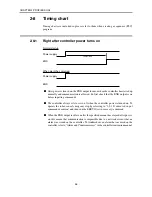
Страница 32: ...at the END output is on before inputting commands The controller always sets to servo off when the controller power is turned on To operate the robot cancel emergency stop by referring to 2 8 2 Dedicated input command execution and then run the SERVO servo recovery command When the END output is off even after the specified amount has elapsed after power on this means that communication is impossi...

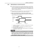
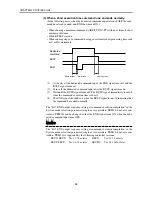
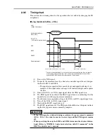
Страница 33: ...on is in progress and the END signal off when the dedicated command input turns off contact open Dedicated command BUSY END 30ms or less 1ms or less 1ms or less 1 At the rise of the dedicated command input the END signal turns off and the BUSY signal turns on 2 Turns off the dedicated command input after the BUSY signal turns on 3 Wait until the BUSY signal turns off 4 The END signal should be on ...

Страница 34: ...nal turns on 3 Wait until the BUSY signal turns off The BUSY signal immediately turns off since the command execution time is short 4 The END signal should be on when the BUSY signal turns off indicating that the command has ended normally The bit 7 END output sequence setting at command execution completion in the System mode selection parameter single axis controllers PRM34 dual axis con troller...

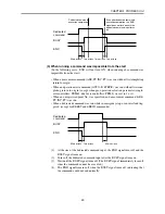
Страница 35: ...o origin except when pre operation selection parameter single axis controllers PRM48 dual axis controllers PRM9 was set to 1 or 3 When an unregistered point No was specified and a movement command ABS PT INC PT was run When a dedicated command was run while in emergency stop or an interlock trig gered except for RESET and SERVO commands Dedicated command BUSY END 30ms or less 1ms or less 30ms or l...

Страница 36: ... was made or some kind of error occurred Dedicated command BUSY END Differs according to execution command Command execution impossible 1 At the rise of the dedicated command input the END signal turns off and the BUSY signal turns on 2 Turns off contact open the dedicated command input after the BUSY signal turns on 3 Wait until the BUSY signal turns off 4 The BUSY signal turns off because the co...

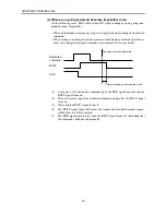
Страница 37: ... signal is input Dedicated command BUSY END LOCK Differs according to execution command Interlock The BUSY output turns OFF when an interlock signal is input during running of a dedicated command The READY output and the END output remain unchanged ...

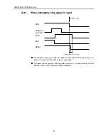
Страница 38: ...END EMG READY 5ms or less 1ms or less Emergency stop The READY output turns OFF The BUSY output turns OFF during running of a dedicated command The END output is unchanged To resume robot operation after canceling emergency stop and checking that the READY output is ON input the SERVO command ...

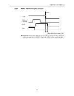
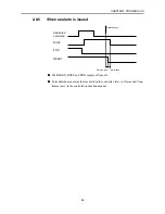
Страница 39: ...issued Dedicated command BUSY END READY 5ms or less 1ms or less Alarm occurs The READY BUSY and END outputs all turn off To troubleshoot an alarm that occurred on the controller refer to Alarm and Coun termeasures in the controller instruction manual ...

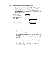
Страница 40: ... INC PT BUSY Actual robot operation END 1 Input the point and speed data into SI200 SI211 To specify a movement axis input the axis designation data into SI213 SI214 Please hold this data until the BUSY signal turns on Changing data while busy may sometimes cause data recognition errors 2 Input the point movement commands ABS PT INC PT after delaying the time to 30 ms or more 3 The END signal turn...

Страница 41: ...efer to 2 9 2 I O assignment list Also refer to 2 9 3 I O assignment selection parameter description for details on the I O assignment selection parameter and 2 9 4 Input output signal description for details on each input output signal used for I O as signment selection After changing the I O assignment the controller must be restarted to enable the changes M E M O M E M O The I O assignment chan...

Страница 42: ... 3 1 Qn 3 2 Qn 3 3 Qn 3 4 Qn 3 5 Qn 3 6 Qn 3 7 Qn 4 0 to Qn 5 7 SERVO INC PT ABS PT STEP R AUTO R RESET ORG S LOCK SVCE EMG SI200 SI201 SI202 SI203 SI204 SI205 SI206 SI207 SI208 SI209 SI210 SI211 SI212 SI213 4 SI214 4 SI215 SI216 to SI231 SERVO INC PT ABS PT RESET ORG S LOCK SVCE EMG PI200 PI201 PI202 PI203 PI204 PI205 4 4 SERVO INC PT ABS PT RESET ORG S LOCK SVCE EMG PI200 PI201 PI202 PI203 SPD20...

Страница 43: ...3 ORG O END BUSY READY PO200 PO201 PO202 PO203 PO204 PO205 Cannot be used 1 The PO output format differs depending on the values in the hundreds and thousands places of the I O assignment selection parameter single axis controllers PRM59 dual axis controllers PRM26 2 Specifies the permissible number of movement points for a point movement command ABS PT INC PT 3 Specifies the permissible number of...

Страница 44: ...nment list Meaning PRM59 PRM26 x x xx e w q q I O assignment type selection 00 20 21 30 31 Description Value Type 0 Conventional type standard Type 2 Point number output type Type 3 Point teaching type M E M O M E M O Type 1 cannot be used with the SRCP SRCD SRCX SRCX and DRCX w Point output selection Make setting only for Type 2 Point number output type or Type 3 Point teaching type 0 1 2 3 Descr...

Страница 45: ...H or later In controller versions prior to the above versions the OUT valid position is the only point zone judgment method Initial value 0 CAUTION Any value other than the above is handled as a 0 Type 0 Example If set to 2331 this is handled as a 0 Type 0 If set to 10 this is handled as a 0 Type 0 Moreover if Type 2 Point number output type or Type 3 Point teaching type is selected in controller ...

Страница 46: ...ith a point movement command ABS PT INC PT or jog movement command JOG JOG For details on the ABS PT and INC PT commands see 2 7 2 Dedicated command input in this chapter The movement speed must be specified before running a point movement com mand or jog movement command See the table below to specify the movement speed Movement speed setting example SPD202 SPD201 OFF ON OFF ON Movement speed 100...

Страница 47: ...ually used for jog movement However the Y axis can be specified with SI213 and SI214 by enabling PRM10 Control axis selection with I O command Refer to PRM10 Control axis selection with I O command in the DRCX controller user s manual Axis selection example SI214 SI213 OFF ON OFF ON JOG JOG Selected axis X axis X axis Y axis X axis OFF OFF ON ON CAUTION If the CHG mode switch input signal is switc...

Страница 48: ...PO when the robot enters the point zone output range corresponding point position judgment parameter range The corresponding point of this point zone output range is the point data registered at the controller Moreover the point zone output range s corresponding point can be further narrowed to correspond to point movement commands ABS PT INC PT with the point number being output to the PO This is...

Страница 49: ...P7 P31 P63 OFF OFF OFF OFF ON PO204 24 OFF OFF OFF ON ON PO203 23 OFF OFF OFF ON ON PO202 22 OFF OFF ON ON ON PO201 21 OFF OFF ON ON ON PO200 20 OFF ON ON ON ON CAUTION When using PO as an output signal that indicates the target position s point number for point movement commands ABS PT INC PT If moving the robot to point 0 with at the first point movement command which is executed after turning t...

Страница 50: ...e therefore turned off at that time Movement points are also reset if a program reset is performed and the movement point zone PO outputs are reset OFF at that time as well Return to origin complete output Zone output 0 ORG O ZONE0 This output notifies that return to origin operation is complete When Zone 0 output is enabled with the Zone output selection parameter single axis controllers PRM53 du...

Страница 51: ...input status specified here must be kept unchanged until step 4 is complete If this input status is changed the controller might misrecognize the data 3 Turn on the JOG or JOG input signal while the CHG signal is on 4 The END signal turns off and the BUSY signal turns on indicating that the controller received the jog movement command 5 The robot moves in jog mode as long as the JOG or JOG input s...

Страница 52: ...t data The point numbers that can be used depend on the I O assignment type Refer to the I O assignment list in 2 9 2 Changing the I O assignment The input status for designating the point number must be kept unchanged until step 3 is complete If this input status is changed the controller might misrecognize the data 2 After 30ms or more has elapsed turn on the PSET 3 The END signal turns off and ...

Страница 53: ...er of movement points Point output selection When I O assignment selection parameter 30 single axis controllers PRM59 dual axis controllers PRM26 Type 3 point teaching type 64 points Point No output to PO when movement ends normally 2 The point numbers of the target positions are designated before running a point movement command ABS PT INC PT Point movement command execution q 1 To specify the mo...

Страница 54: ...rst executed after turning on the controller all of PO200 to PO205 still remain off because P0 000000 binary even after the robot has moved to point 0 This means that the PO200 to PO205 status does not change even after the robot has moved to P0 so no information is available to indicate whether the robot motion to P0 is complete or whether the movement command was received This should be kept in ...

Страница 55: ...ints Point output selection When I O assignment selection parameter 130 single axis controllers PRM59 dual axis controllers PRM26 Type 3 point teaching type 64 points Point No output to PO when movement command is received 2 The point numbers of the target positions are designated before running a point movement command ABS PT INC PT Point movement command execution q 1 To specify the movement axi...

Страница 56: ...t with a point movement com mand that is first executed after turning on the controller all of PO200 to PO205 still remain off because P0 000000 binary even after the robot has moved to point 0 This means that the PO200 to PO205 status does not change even after specifying P0 as the target position so no information is available to indicate whether the movement command to P0 was received This shou...

Страница 57: ...ignment type q w e r t X b b P900 P900 P900 P901 P901 P902 P902 P903 P903 P903 Pn Y PO 203 23 PO 202 22 PO 201 21 PO 200 20 Point zone output range Point zone output range Zone output range Zone output range For single axis type For dual axis type Precondition 1 The following steps are explained assuming that the I O assign ment selection parameter single axis controllers PRM59 dual axis controlle...

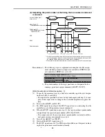
Страница 58: ...int judgment method can be set to either OUT valid position or Posi tioning completed pulse this is specified in the thousands place of the I O as signment selection parameter In controllers prior to the following versions the point zone judgment method specified by the position judgment parameter can only be set to OUT valid position ERCX SRCX Ver 13 64 or later DRCX Ver 18 64 or later SRCP SRCD ...

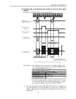
Страница 59: ... are explained assuming that the I O assign ment selection parameter single axis controllers PRM59 dual axis controllers PRM26 is set to 321 I O assignment type Permissible number of movement points Point output selection Point zone judgment method position judgment parameter When I O assignment selection parameter 321 single axis controllers PRM59 dual axis controllers PRM26 Type 2 Point No outpu...

Страница 60: ...ts are reset immediately after a controller power on all PO outputs turn off Movement points are also reset when the RESET command is executed and movement point zone outputs by PO are cleared The position judgment parameter for selecting the point zone judgment method can be set to either OUT valid position or Positioning completed pulse this is speci fied in the thousands place of the I O assign...

Страница 61: ...ns are not met the command ends at the stage the robot reaches the specified point and proceeds to the next step 1 Point numbers Point numbers are identifying numbers assigned to 1 000 points in a range from 0 to 999 These point numbers are used to create point data in point mode As a special usage method when a character called P is input here a point variable defined by the P character is set in...

Страница 62: ...ral purpose input or a serial general purpose input is considered a binary input value and the jump is performed if it matches the input value conditions The number of points that can be sub grouped by input condition depends on the number of conditional input points The number of conditional input points is set by the conditional input point parameter single axis controllers PRM8 dual axis contro...

Страница 63: ...1 number from among the general purpose inputs 0 15 16 points or memory input 100 147 48 points or the serial general purpose inputs 200 231 32 points 3 Input status Here 1 means ON and 0 means OFF 0 to 7 8 points for the SRCP SRCD series controllers 2 10 4 DO Function Turns the general purpose output or memory output or serial general purpose output on or off Format DO DO or MO or SO No Output st...

Страница 64: ...N Explanation The WAIT command adjusts the timing according to the status of the general purpose input or memory input or serial general purpose input 1 DI or MI or SI numbers Specifies one from among the general purpose inputs 0 15 16 points or memory input 100 147 48 points or the serial general purpose outputs 200 231 32 points 2 Input status Here 1 means the input is ON and 0 means the input i...

Страница 65: ...lization Controller Sequencer PLC Sequencer PLC Sensors etc Grippers etc PROFIBUS SI200 212 SO200 215 DI0 15 DO0 12 3 2 1 4 More specifically when emulated serialization is only for DI1 the DI1 status is output to SO201 Output of SO201 with the DO statement is disabled at this time DI0 DI2 DI15 and SO200 SO202 SO215 can be used as normal input outputs The DO statement is invalid on output ports th...

Страница 66: ...the DI No you want to set If the DI No you want to set is not shown just press the F4 next as many times as needed to select DI3 DI15 5 This is the screen when F2 S DO was selected above in step 3 The DO12 DO0 current settings appear on the screen from the left side Here 0 indi cates normal status and 1 indicates a emulated serialization setting To change a setting press the function key displayin...

Страница 67: ...the remote command The option data is set at QWn 12 to QWn 22 Since the number of options size and setting address of the command option are different in each command refer to 2 12 3 Remote command details robot operation and the subsequent sections Similarly some commands return the data to the master sequencer PLC side as the response In this case the response data is set at IWm 12 to Wm 22 Like...

Страница 68: ...01 0102 0103 0104 0105 0106 0107 0108 0109 010A 010B Return to origin execution Program reset Automatic operation start Step operation start Servo status change JOG movement inching JOG movement Direct position specification movement execution Position specification movement execution Movement stroke specification movement execution General purpose input response movement execution Axis Axis Statu...

Страница 69: ... counter arrangement variable C Counter variable D definition Addition of specified value to counter variable D Subtraction of specified value from counter variable D Shift execution of position data Linear interpolation movement execution Circular interpolation movement execution Axis Pallet work position Speed Axis Specified position Axis Specified distance DO MO SO number 0 or 1 DI MI SI number...

Страница 70: ...tatus read Specified parameter data read Specified point data read Axis Axis Axis Pallet number Arrangement element No DI MI SI number DO MO SO number Parameter number Point number QWn 12 QWn 12 QWn 12 QWn 12 QWn 12 QWn 12 QWn 12 QWn 12 QWn 12 X axis position Y axis position Program number Step number Task number Point number Version value Axis number Emergency stop status Servo status Return to o...

Страница 71: ...Wn 18 QWn 16 QWn 12 QWn 14 QWn 18 QWn 16 QWn 22 QWn 20 Remote Command QWn 8 Code No Option response register register Command response Command option Command details 4 Special commands 1 2 0000 0401 No execution status clear Response register initialization Initial value data QWn 22 QWn 20 QWn 18 QWn 16 QWn 14 QWn 12 Initial status IWm 22 IWm 20 IWm 18 IWm 16 IWm 14 IWm 12 Remote Command QWn 8 Cod...

Страница 72: ...0 0101 Response example 1 It is normally ended IWm 22 IWm 20 IWm 18 IWm 16 IWm 14 IWm 12 IWm 10 IWm 8 0000 0000 0000 0000 0000 0000 0000 0200 Response example 2 Origin incomplete occurs since the return to origin is not com pleted in the axis of the mark system IWm 22 IWm 20 IWm 18 IWm 16 IWm 14 IWm 12 IWm 10 IWm 8 0000 0000 0000 0000 0000 0000 0000 4020 M E M O M E M O If any axis of the mark sys...

Страница 73: ...on during origin detection mechanical limit in contact The alarm stop results from the overload of the controller and it is necessary to turn ON the power supply again CAUTION If return to origin of the stroke end origin system is inevitably repeated provide an interval of 5 seconds or more between the repeated operations ...

Страница 74: ... I O any output does not vary even if the reset command is executed CAUTION If the return to origin completing operation selection parameter single axis controllers PRM33 dual axis controllers PRM2 is set to 1 or 3 DO4 2 will not be turned OFF even if the reset command is executed If the servo status output selection parameter single axis controllers PRM46 dual axis controllers PRM21 is set to 1 D...

Страница 75: ... It is executed to the final step IWm 22 IWm 20 IWm 18 IWm 16 IWm 14 IWm 12 IWm 10 IWm 8 0000 0000 0000 0000 0000 0000 0000 0200 Response example 2 The origin incomplete error occurs to interrupt the robot opera tion IWm 22 IWm 20 IWm 18 IWm 16 IWm 14 IWm 12 IWm 10 IWm 8 0000 0000 0000 0000 0000 0000 0000 4020 CAUTION If any endless program in which it unconditionally return to the program head fr...

Страница 76: ... Transmission example 1 The step operation is started QWn 22 QWn 20 QWn 18 QWn 16 QWn 14 QWn 12 QWn 10 QWn 8 0000 0000 0000 0000 0000 0000 0000 0104 Response example 1 The step operation is completely executed IWm 22 IWm 20 IWm 18 IWm 16 IWm 14 IWm 12 IWm 10 IWm 8 0000 0000 0000 0000 0000 0000 0000 0200 Response example 2 The origin incomplete error occurs to interrupt the robot opera tion IWm 22 ...

Страница 77: ... X axis and 2 meansY axis On dual axis controllers all axes are also specified when 3 is set On single axis controllers 0 or 1 alone can be specified Status 1 means servo ON and 0 means servo OFF Example Transmission example 1 Servo OFF is set for all axes QWn 22 QWn 20 QWn 18 QWn 16 QWn 14 QWn 12 QWn 10 QWn 8 0000 0000 0000 0000 0000 0000 0000 0105 Response example 1 It is normally ended IWm 22 I...

Страница 78: ...s and 2 means Y axis On single axis controllers 1 alone can be specified Direction 0 means direction and 1 means direction Example Transmission example 1 Y axis is moved only at the specified stroke in the direction QWn 22 QWn 20 QWn 18 QWn 16 QWn 14 QWn 12 QWn 10 QWn 8 0000 0000 0000 0000 0001 0001 0000 0106 Response example 1 It is normally ended IWm 22 IWm 20 IWm 18 IWm 16 IWm 14 IWm 12 IWm 10 ...

Страница 79: ... 0 means direction and 1 means direction Example Transmission example 1 Y axis is moved only at the specified speed in the direction QWn 22 QWn 20 QWn 18 QWn 16 QWn 14 QWn 12 QWn 10 QWn 8 0000 0000 0000 0000 0001 0001 0000 0107 Response example 1 It reaches the software limit and is normally ended IWm 22 IWm 20 IWm 18 IWm 16 IWm 14 IWm 12 IWm 10 IWm 8 0000 0000 0000 0000 0000 0000 0000 0200 CAUTIO...

Страница 80: ...ent position is 0 01 degrees When the axis is specified the axis data is free for any other axis not specified Similarly it does not matter that the data of Y axis is free on single axis controllers Example Transmission example 1 In the current position indication mode it moves to the position of X 50 37 and Y 45 55 at the 100 speed QWn 22 QWn 20 QWn 18 QWn 16 QWn 14 QWn 12 QWn 10 QWn 8 0000 11CB ...

Страница 81: ... variable P register 4095 0FFF hexadecimal Speed It can be set at 100 intervals from 1 to 100 and 100 3000rpm if the program execution speed parameter 1 is set to 100 In this case the maximum speed setting parameter 2 is set to 3000 Example Transmission example 1 It moves to the position of P123 at the speed 100 QWn 22 QWn 20 QWn 18 QWn 16 QWn 14 QWn 12 QWn 10 QWn 8 0000 0000 0000 0064 007B 0000 0...

Страница 82: ... 100 In this case the maximum speed setting parameter 2 is set to 3000 Example Transmission example 1 It moves from the current position by the P123 stroke alone at the speed 100 QWn 22 QWn 20 QWn 18 QWn 16 QWn 14 QWn 12 QWn 10 QWn 8 0000 0000 0000 0064 007B 0000 0000 010A Response example 1 It is normally ended IWm 22 IWm 20 IWm 18 IWm 16 IWm 14 IWm 12 IWm 10 IWm 8 0000 0000 0000 0000 0000 0000 0...

Страница 83: ...his is the inherent number assigned to each of 1000 points as a total from 0 to 999 To specify the point variable P register 4095 0FFF hexadecimal DI SI number Specify one among the general purpose input DI0 to 15 1 and SI200 to 231 DI SI status 1 means ON and 0 means OFF Example Transmission example 1 Y axis alone is continuously moved to the position of P2 until SI210 1 ON QWn 22 QWn 20 QWn 18 Q...

Страница 84: ...100 In this case the maximum speed setting parameter 2 is set to 3000 Example Transmission example 1 If the matrix of 4 3 is defined it moves to the 2nd line and 2nd array at the speed 100 QWn 22 QWn 20 QWn 18 QWn 16 QWn 14 QWn 12 QWn 10 QWn 8 0000 0000 0000 0064 0005 0000 0000 010C Response example 1 It is normally ended IWm 22 IWm 20 IWm 18 IWm 16 IWm 14 IWm 12 IWm 10 IWm 8 0000 0000 0000 0000 0...

Страница 85: ...pecified position It is the movement position absolute position of origin reference of the arch motion execution axis The position can be specified in the range of 9999 to 9999 in the millimeter units Example Transmission example 1 The arch motion in which Y axis returns to Y 10 00 is defined QWn 22 QWn 20 QWn 18 QWn 16 QWn 14 QWn 12 QWn 10 QWn 8 0000 0000 0000 0000 000A 0002 0000 010D Response ex...

Страница 86: ...e range of 9999 to 9999 in the millimeter units Example Transmission example 1 The arch motion in which Y axis returns by 100 00 is defined QWn 22 QWn 20 QWn 18 QWn 16 QWn 14 QWn 12 QWn 10 QWn 8 0000 0000 0000 0000 FF9C 0002 0000 010E Response example 1 It is normally ended IWm 22 IWm 20 IWm 18 IWm 16 IWm 14 IWm 12 IWm 10 IWm 8 0000 0000 0000 0000 0000 0000 0000 0200 CAUTION This command is invali...

Страница 87: ...fied among the general purpose output 0 to 12 13 points serial general purpose output 200 to 231 32 points or memory output 100 to 131 32 points Output status 1 means ON and 0 means OFF Example Transmission example 1 The serial general purpose output 203 is turned ON QWn 22 QWn 20 QWn 18 QWn 16 QWn 14 QWn 12 QWn 10 QWn 8 0000 0000 0000 0000 0001 00CB 0000 010F Response example 1 It is normally end...

Страница 88: ...SI number One is specified among the general purpose input 0 to 15 16 points serial general purpose input 200 to 231 32 points or memory input 100 to 147 48 points Input status 1 means ON and 0 means OFF Example Transmission example 1 It waits until SI201 1 QWn 22 QWn 20 QWn 18 QWn 16 QWn 14 QWn 12 QWn 10 QWn 8 0000 0000 0000 0000 0001 00C9 0000 0110 Response example 1 It is normally ended IWm 22 ...

Страница 89: ...m 18 IWm 16 IWm 14 IWm 12 Details Time It can be specified in the range of 1 to 65535 in the 10 millisecond units Example Transmission example 1 It waits for 1 second QWn 22 QWn 20 QWn 18 QWn 16 QWn 14 QWn 12 QWn 10 QWn 8 0000 0000 0000 0000 0000 0064 0000 0111 Response example 1 It is normally ended IWm 22 IWm 20 IWm 18 IWm 16 IWm 14 IWm 12 IWm 10 IWm 8 0000 0000 0000 0000 0000 0000 0000 0200 ...

Страница 90: ...er Line number A value of 1 to 255 can be applied to each matrix Pallet number It is the inherent number of 0 to 31 for the matrix discrimination Example Transmission example 1 The matrix of 5 2 is defined at the 1st number QWn 22 QWn 20 QWn 18 QWn 16 QWn 14 QWn 12 QWn 10 QWn 8 0000 0000 0000 0001 0002 0005 0000 0112 Response example 1 It is normally ended IWm 22 IWm 20 IWm 18 IWm 16 IWm 14 IWm 12...

Страница 91: ...mber Command response IWm 22 IWm 20 IWm 18 IWm 16 IWm 14 IWm 12 Details Pallet number It is the inherent number of 0 to 31 for matrix discrimination Example Transmission example 1 The matrix of the pallet No 0 is specified QWn 22 QWn 20 QWn 18 QWn 16 QWn 14 QWn 12 QWn 10 QWn 8 0000 0000 0000 0000 0000 0000 0000 0113 Response example 1 It is normally ended IWm 22 IWm 20 IWm 18 IWm 16 IWm 14 IWm 12 ...

Страница 92: ... QWn 12 QWn 10 QWn 8 0000 0000 0000 0000 0000 0064 0000 0114 Response example 1 It is normally ended IWm 22 IWm 20 IWm 18 IWm 16 IWm 14 IWm 12 IWm 10 IWm 8 0000 0000 0000 0000 0000 0000 0000 0200 M E M O M E M O Since the point variable is prepared to treat the point number as the variable a value of 0 to 999 can be specified CAUTION Though the content of the point variable is held even if the con...

Страница 93: ...ommand response IWm 22 IWm 20 IWm 18 IWm 16 IWm 14 IWm 12 Details Addition value A value of 1 to 999 can be specified Example Transmission example 1 10 is added to the point variable P QWn 22 QWn 20 QWn 18 QWn 16 QWn 14 QWn 12 QWn 10 QWn 8 0000 0000 0000 0000 0000 000A 0000 0115 Response example 1 It is normally ended IWm 22 IWm 20 IWm 18 IWm 16 IWm 14 IWm 12 IWm 10 IWm 8 0000 0000 0000 0000 0000 ...

Страница 94: ...e Command response IWm 22 IWm 20 IWm 18 IWm 16 IWm 14 IWm 12 Details Subtraction value A value of 1 to 999 can be specified Example Transmission example 1 10 is subtracted from the point variable P QWn 22 QWn 20 QWn 18 QWn 16 QWn 14 QWn 12 QWn 10 QWn 8 0000 0000 0000 0000 0000 000A 0000 0116 Response example 1 It is normally ended IWm 22 IWm 20 IWm 18 IWm 16 IWm 14 IWm 12 IWm 10 IWm 8 0000 0000 00...

Страница 95: ...sses the inherent number of 0 to 31 to specify the arrange ment element of the counter arrangement variable If 65534 FFFE hexadecimal is input here the value in the counter variable D is used to specify the element of the counter variable Example Transmission example 1 Hereafter the counter arrangement variable of the element No 1 is used QWn 22 QWn 20 QWn 18 QWn 16 QWn 14 QWn 12 QWn 10 QWn 8 0000...

Страница 96: ...16 IWm 14 IWm 12 Details Counter value A value of 0 to 65535 can be specified Example Transmission example 1 200 is set at the counter arrangement variable C QWn 22 QWn 20 QWn 18 QWn 16 QWn 14 QWn 12 QWn 10 QWn 8 0000 0000 0000 0000 0000 00C8 0000 0118 Response example 1 It is normally ended IWm 22 IWm 20 IWm 18 IWm 16 IWm 14 IWm 12 IWm 10 IWm 8 0000 0000 0000 0000 0000 0000 0000 0200 M E M O M E ...

Страница 97: ...n 18 QWn 16 QWn 14 QWn 12 Addition value Command response IWm 22 IWm 20 IWm 18 IWm 16 IWm 14 IWm 12 Details Addition value A value of 1 to 65535 can be specified Example Transmission example 1 10 is added to the counter arrangement variable C QWn 22 QWn 20 QWn 18 QWn 16 QWn 14 QWn 12 QWn 10 QWn 8 0000 0000 0000 0000 0000 000A 0000 0119 Response example 1 It is normally ended IWm 22 IWm 20 IWm 18 I...

Страница 98: ...Wn 18 QWn 16 QWn 14 QWn 12 Subtraction value Command response IWm 22 IWm 20 IWm 18 IWm 16 IWm 14 IWm 12 Details Addition value A value of 1 to 65535 can be specified Example Transmission example 1 10 is subtracted from the counter arrangement variable C QWn 22 QWn 20 QWn 18 QWn 16 QWn 14 QWn 12 QWn 10 QWn 8 0000 0000 0000 0000 0000 000A 0000 011A Response example 1 It is normally ended IWm 22 IWm ...

Страница 99: ...0 to 65535 can be specified Example Transmission example 1 200 is set to the counter variable D QWn 22 QWn 20 QWn 18 QWn 16 QWn 14 QWn 12 QWn 10 QWn 8 0000 0000 0000 0000 0000 00C8 0000 011B Response example 1 It is normally ended IWm 22 IWm 20 IWm 18 IWm 16 IWm 14 IWm 12 IWm 10 IWm 8 0000 0000 0000 0000 0000 0000 0000 0200 M E M O M E M O The counter variable D is a variable which can be set as d...

Страница 100: ...ommand response IWm 22 IWm 20 IWm 18 IWm 16 IWm 14 IWm 12 Details Addition value A value of 1 to 65535 can be specified Example Transmission example 1 10 is added to the counter variable D QWn 22 QWn 20 QWn 18 QWn 16 QWn 14 QWn 12 QWn 10 QWn 8 0000 0000 0000 0000 0000 000A 0000 011C Response example 1 It is normally ended IWm 22 IWm 20 IWm 18 IWm 16 IWm 14 IWm 12 IWm 10 IWm 8 0000 0000 0000 0000 0...

Страница 101: ...ue Command response IWm 22 IWm 20 IWm 18 IWm 16 IWm 14 IWm 12 Details Addition value A value of 1 to 65535 can be specified Example Transmission example 1 10 is subtracted from the counter variable D QWn 22 QWn 20 QWn 18 QWn 16 QWn 14 QWn 12 QWn 10 QWn 8 0000 0000 0000 0000 0000 000A 0000 011D Response example 1 It is normally ended IWm 22 IWm 20 IWm 18 IWm 16 IWm 14 IWm 12 IWm 10 IWm 8 0000 0000 ...

Страница 102: ... IWm 14 IWm 12 Details Point number It is the inherent number which is assigned to a total of 1000 points of 0 to 999 To specify the point variable P register 4095 0FFF hexadecimal Example Transmission example 1 Hereafter the position data is shifted by the data of the point 1 during movement QWn 22 QWn 20 QWn 18 QWn 16 QWn 14 QWn 12 QWn 10 QWn 8 0000 0000 0000 0000 0000 0001 0000 011E Response ex...

Страница 103: ...shed When the maximum speed setting parameter 2 is 3000 and the lead length is 20mm Example Transmission example 1 It moves to the P123 position at the speed 20 in the linear inter polation mode QWn 22 QWn 20 QWn 18 QWn 16 QWn 14 QWn 12 QWn 10 QWn 8 0000 0000 0000 0014 007B 0000 0000 011F Response example 1 It is normally ended IWm 22 IWm 20 IWm 18 IWm 16 IWm 14 IWm 12 IWm 10 IWm 8 0000 11CB 0000 ...

Страница 104: ...n the program execu tion speed parameter 1 is 100 100 1000mm s is established When the maximum speed setting parameter 2 is 3000 and the lead length is 20mm Locus specification The locus type is selected 0 Circular segment 1 Circle Example Transmission example 1 It moves at the speed 20 on the circular locus where the start point is the current position the point 123 is passed and the point 124 is...

Страница 105: ...plicable radius is max 1000mm and min 2mm CAUTION The SCARA robot etc which do not operate in the cartesian coordinates cannot be moved in the circular interpolation mode 1 Single axis controllers PRM30 dual axis controllers PRM17 2 Single axis controllers PRM44 dual axis controllers PRM64 and PRM104 ...

Страница 106: ...robot is set at the rotary axis the unit of the movement position is 0 01 degrees Single axis controllers does not use IWm 20 to IWm 22 Similarly writing is not applied to the unspecified axis with the command option Example Transmission example 1 The current position information of all axes is read QWn 22 QWn 20 QWn 18 QWn 16 QWn 14 QWn 12 QWn 10 QWn 8 0000 0000 0000 0000 0000 0000 0000 0201 Resp...

Страница 107: ...IWm 14 IWm 12 Program number Details Program number It is the inherent number of 0 to 99 assigned to each program Example Transmission example 1 The execution program is read QWn 22 QWn 20 QWn 18 QWn 16 QWn 14 QWn 12 QWn 10 QWn 8 0000 0000 0000 0000 0000 0000 0000 0202 Response example 1 No 31 is being executed IWm 22 IWm 20 IWm 18 IWm 16 IWm 14 IWm 12 IWm 10 IWm 8 0000 0000 0000 0000 0000 001F 00...

Страница 108: ... IWm 12 Step number Details Step number It is the inherent value of 1 to 255 assigned to each step Example Transmission example 1 The execution step number is read QWn 22 QWn 20 QWn 18 QWn 16 QWn 14 QWn 12 QWn 10 QWn 8 0000 0000 0000 0000 0000 0000 0000 0203 Response example 1 The 170th line is being executed IWm 22 IWm 20 IWm 18 IWm 16 IWm 14 IWm 12 IWm 10 IWm 8 0000 0000 0000 0000 0000 00AA 0000...

Страница 109: ...4 IWm 12 Task number Details Task number It is the inherent number of 0 to 3 assigned to each task Example Transmission example 1 The execution task number is read QWn 22 QWn 20 QWn 18 QWn 16 QWn 14 QWn 12 QWn 10 QWn 8 0000 0000 0000 0000 0000 0000 0000 0204 Response example 1 The currently selected task is 0 main task IWm 22 IWm 20 IWm 18 IWm 16 IWm 14 IWm 12 IWm 10 IWm 8 0000 0000 0000 0000 0000...

Страница 110: ...igned to each point Example Transmission example 1 The current point number is read QWn 22 QWn 20 QWn 18 QWn 16 QWn 14 QWn 12 QWn 10 QWn 8 0000 0000 0000 0000 0000 0000 0000 0205 Response example 1 The point number currently selected is 57 IWm 22 IWm 20 IWm 18 IWm 16 IWm 14 IWm 12 IWm 10 IWm 8 0000 0000 0000 0000 0000 0039 0000 0200 M E M O M E M O It is used to know what point number was used for...

Страница 111: ...d by the controller If the version is V13 30 1330 532 hexadecimal is indicated Example Transmission example 1 The controller system version is read QWn 22 QWn 20 QWn 18 QWn 16 QWn 14 QWn 12 QWn 10 QWn 8 0000 0000 0000 0000 0000 0000 0000 0206 Response example 1 The version is V13 30 IWm 22 IWm 20 IWm 18 IWm 16 IWm 14 IWm 12 IWm 10 IWm 8 0000 0000 0000 0000 0000 0532 0000 0200 M E M O M E M O The c...

Страница 112: ...mmand response IWm 22 IWm 20 IWm 18 IWm 16 IWm 14 IWm 12 Axis number Example Transmission example 1 The total number of axes is read QWn 22 QWn 20 QWn 18 QWn 16 QWn 14 QWn 12 QWn 10 QWn 8 0000 0000 0000 0000 0000 0000 0000 0207 Response example 1 2 axes are operable IWm 22 IWm 20 IWm 18 IWm 16 IWm 14 IWm 12 IWm 10 IWm 8 0000 0000 0000 0000 0000 0002 0000 0200 ...

Страница 113: ...op Details Emergency stop 1 means the emergency stop status and 0 means that the emer gency stop is canceled Example Transmission example 1 The status of the emergency stop is read QWn 22 QWn 20 QWn 18 QWn 16 QWn 14 QWn 12 QWn 10 QWn 8 0000 0000 0000 0000 0000 0000 0000 0208 Response example 1 0 the emergency stop is canceled is established IWm 22 IWm 20 IWm 18 IWm 16 IWm 14 IWm 12 IWm 10 IWm 8 00...

Страница 114: ...xis 0 means all axes 1 means X axis and 2 meansY axis On dual axis controllers all axes are also specified when 3 is set On single axis controllers 0 or 1 alone can be specified Servo status 1 means the servo on and 0 means the servo off Example Transmission example 1 The servo statuses of all axes are read QWn 22 QWn 20 QWn 18 QWn 16 QWn 14 QWn 12 QWn 10 QWn 8 0000 0000 0000 0000 0000 0000 0000 0...

Страница 115: ...ns all axes 1 means X axis and 2 meansY axis On dual axis controllers all axes are also specified when 3 is set On single axis controllers 0 or 1 alone can be specified Origin status 0 means that the origin is incomplete and 1 means that the return to origin is completed Example Transmission example 1 It reads that the return to origin is completed in all axes QWn 22 QWn 20 QWn 18 QWn 16 QWn 14 QW...

Страница 116: ...4 IWm 12 Status Details Status 1 means that the servo mode is valid and 0 means that it is invalid Example Transmission example 1 The service mode status is read QWn 22 QWn 20 QWn 18 QWn 16 QWn 14 QWn 12 QWn 10 QWn 8 0000 0000 0000 0000 0000 0000 0000 020B Response example 1 1 service mode status is established IWm 22 IWm 20 IWm 18 IWm 16 IWm 14 IWm 12 IWm 10 IWm 8 0000 0000 0000 0000 0000 0001 00...

Страница 117: ...PB personal computer etc 2 The program is being executed with I O command Example Transmission example 1 The robot status is read QWn 22 QWn 20 QWn 18 QWn 16 QWn 14 QWn 12 QWn 10 QWn 8 0000 0000 0000 0000 0000 0000 0000 020C Response example 1 0 stop status is established IWm 22 IWm 20 IWm 18 IWm 16 IWm 14 IWm 12 IWm 10 IWm 8 0000 0000 0000 0000 0000 0000 0000 0200 CAUTION The data handling with t...

Страница 118: ...etails Pallet number It is the inherent number of 0 to 31 for matrix discrimination Array number Line number It is the value of 1 to 255 Example Transmission example 1 The data of the pallet No 1 is read QWn 22 QWn 20 QWn 18 QWn 16 QWn 14 QWn 12 QWn 10 QWn 8 0000 0000 0000 0000 0000 0001 0000 020D Response example 1 It is the matrix of line number 20 and array number 30 IWm 22 IWm 20 IWm 18 IWm 16...

Страница 119: ...let number Details Pallet number It is the inherent number of 0 to 31 for matrix discrimination Array number Line number It is the value of 1 to 255 Example Transmission example 1 The currently specified pallet number is read QWn 22 QWn 20 QWn 18 QWn 16 QWn 14 QWn 12 QWn 10 QWn 8 0000 0000 0000 0000 0000 0000 0000 020E Response example 1 The pallet 0 is specified IWm 22 IWm 20 IWm 18 IWm 16 IWm 14...

Страница 120: ... 1 The point variable P is read QWn 22 QWn 20 QWn 18 QWn 16 QWn 14 QWn 12 QWn 10 QWn 8 0000 0000 0000 0000 0000 0000 0000 020F Response example 1 The point variable is P 100 IWm 22 IWm 20 IWm 18 IWm 16 IWm 14 IWm 12 IWm 10 IWm 8 0000 0000 0000 0000 0000 0064 0000 0200 CAUTION Though the content of the point variable P is held even when the controller power supply is turned off the point variable P...

Страница 121: ...8 QWn 16 QWn 14 QWn 12 Command response IWm 22 IWm 20 IWm 18 IWm 16 IWm 14 IWm 12 Element No Example Transmission example 1 The element number of the counter arrangement variable C is read QWn 22 QWn 20 QWn 18 QWn 16 QWn 14 QWn 12 QWn 10 QWn 8 0000 0000 0000 0000 0000 0000 0000 0210 Response example 1 The element No is 31 IWm 22 IWm 20 IWm 18 IWm 16 IWm 14 IWm 12 IWm 10 IWm 8 0000 0000 0000 0000 0...

Страница 122: ...IWm 22 IWm 20 IWm 18 IWm 16 IWm 14 IWm 12 Counter value Details Element No The number specifies the arrangement element in the range of 0 to 31 Example Element No The value of the counter arrangement variable C is read QWn 22 QWn 20 QWn 18 QWn 16 QWn 14 QWn 12 QWn 10 QWn 8 0000 0000 0000 0000 0000 0000 0000 0211 Response example 1 The element No is 21202 IWm 22 IWm 20 IWm 18 IWm 16 IWm 14 IWm 12 I...

Страница 123: ...mand response IWm 22 IWm 20 IWm 18 IWm 16 IWm 14 IWm 12 Counter value Example Transmission example 1 The value of the counter variable D is read QWn 22 QWn 20 QWn 18 QWn 16 QWn 14 QWn 12 QWn 10 QWn 8 0000 0000 0000 0000 0000 0000 0000 0212 Response example 1 The element No is 65535 IWm 22 IWm 20 IWm 18 IWm 16 IWm 14 IWm 12 IWm 10 IWm 8 0000 0000 0000 0000 0000 FFFF 0000 0200 ...

Страница 124: ...hift data is indicated unit 0 01mm When the robot is set at the rotary axis the unit of the position is 0 01 degrees Single axis controllers does not use IWm 20 to IWm 22 Example Transmission example 1 The current shift data is read QWn 22 QWn 20 QWn 18 QWn 16 QWn 14 QWn 12 QWn 10 QWn 8 0000 0000 0000 0000 0000 0000 0000 0213 Response example 1 The shift data is X 150 00 Y 250 00 IWm 22 IWm 20 IWm...

Страница 125: ...specified among the general purpose input 0 to 15 16 points memory input 100 to 147 48 points and serial gen eral purpose input 200 to 231 32 points Input status 1 means ON and 0 means OFF Example Transmission example 1 The status of SI201 is read QWn 22 QWn 20 QWn 18 QWn 16 QWn 14 QWn 12 QWn 10 QWn 8 0000 0000 0000 0000 0000 00C9 0000 0214 Response example 1 The SI201 status is SI201 1 ON IWm 22 ...

Страница 126: ...specified among the general purpose output 0 to 12 13 points memory output 100 to 131 32 points and serial general purpose output 200 to 231 32 points Output status 1 means ON and 0 means OFF Example Transmission example 1 The status of SO202 is read QWn 22 QWn 20 QWn 18 QWn 16 QWn 14 QWn 12 QWn 10 QWn 8 0000 0000 0000 0000 0000 00CA 0000 0215 Response example 1 The SO202 status is SO202 0 OFF IWm...

Страница 127: ...ils Parameter number The inherent number assigned to each parameter is 0 to 63 for single axis controllers and is 0 to 127 for dual axis controllers Example Transmission example 1 Y axis transfer mass parameter PRM90 is read QWn 22 QWn 20 QWn 18 QWn 16 QWn 14 QWn 12 QWn 10 QWn 8 0000 0000 0000 0000 0000 005A 0000 0216 Response example 1 The parameter is PRM90 5 kg IWm 22 IWm 20 IWm 18 IWm 16 IWm 1...

Страница 128: ...m 14 IWm 12 Y axis position X axis position Details Point number It is the inherent number of 0 to 999 assigned to each point Example Transmission example 1 Data of P254 is read QWn 22 QWn 20 QWn 18 QWn 16 QWn 14 QWn 12 QWn 10 QWn 8 0000 0000 0000 0000 0000 00FE 0000 0217 Response example 1 The shift data is X 0 05 Y 0 01 IWm 22 IWm 20 IWm 18 IWm 16 IWm 14 IWm 12 IWm 10 IWm 8 0000 0001 FFFF FFFB 0...

Страница 129: ...pplied Command option QWn 22 QWn 20 QWn 18 QWn 16 QWn 14 QWn 12 Program number Command response IWm 22 IWm 20 IWm 18 IWm 16 IWm 14 IWm 12 Details Program number It is the inherent number of 0 to 99 assigned to each program Example Transmission example 1 The program is switched to NO31 QWn 22 QWn 20 QWn 18 QWn 16 QWn 14 QWn 12 QWn 10 QWn 8 0000 0000 0000 0000 0000 001F 0000 0301 Response example 1 ...

Страница 130: ...16 QWn 14 QWn 12 Task number Command response IWm 22 IWm 20 IWm 18 IWm 16 IWm 14 IWm 12 Details Task number It is the inherent number of 0 to 3 assigned to each task Example Transmission example 1 Task is switched to 1 QWn 22 QWn 20 QWn 18 QWn 16 QWn 14 QWn 12 QWn 10 QWn 8 0000 0000 0000 0000 0000 0001 0000 0302 Response example 1 The specified task is not executed IWm 22 IWm 20 IWm 18 IWm 16 IWm ...

Страница 131: ...each parameter is 0 to 63 for single axis controllers and is 0 to 127 for dual axis controllers Parameter data For the parameter data refer to Chapter 5 Parameters of each controller manual Example Transmission example 1 TheY axis transfer mass parameter PRM90 is set to 3 kilograms QWn 22 QWn 20 QWn 18 QWn 16 QWn 14 QWn 12 QWn 10 QWn 8 0000 0000 0000 0003 0000 005A 0000 0303 Response example 1 It ...

Страница 132: ...ngle axis controllers 0 or 1 alone can be specified Axis data The position data desired to register is directly specified Unit 0 01 mm When the rotary axis is set for the robot the unit of the movement position is 0 01 degrees If any axis is specified the data of other axes not specified is free It does not matter that the data of Y axis is free in single axis controllers Example Transmission exam...

Страница 133: ... will be initialized Command option QWn 22 QWn 20 QWn 18 QWn 16 QWn 14 QWn 12 Copy source data Command response IWm 22 IWm 20 IWm 18 IWm 16 IWm 14 IWm 12 Copy destination data Details Copy data The data in the option register QWn 12 to QWn 22 is copied to IWm 12 to IWm 22 Example Transmission example 1 The response register is initialized QWn 22 QWn 20 QWn 18 QWn 16 QWn 14 QWn 12 QWn 10 QWn 8 0000...

Страница 134: ...icates that the controller normally completes the remote command Code 40xx Command error occurrence It indicates that an error occurs and the execution of the remote command cannot be normally completed The occurrence error number is set at the area of xx For example if the 403E code is sent to the sequencer PLC side it indicates from 3E hexadecimal 62 decimal that the command is interrupted by th...

Страница 135: ...current position of the robot is X 321 05 and Y 0 02 IWm 22 IWm 20 IWm 18 IWm 16 IWm 14 IWm 12 IWm 10 IWm 8 FFFF FFFE 0000 7D69 0000 0000 0000 0000 Transmission example 2 Move to the position of X 50 37 and Y 45 55 at the 100 speed in the current position indication mode QWn 22 QWn 20 QWn 18 QWn 16 QWn 14 QWn 12 QWn 10 QWn 8 0000 11CB 0000 13AD 0064 0000 0001 0108 Response example 2 Moving to the ...

Страница 136: ...ry for movement are set at the specified addresses in QWn 12 to QWn 22 before the command is set to QWn 8 or at the same time when the command is set 0000 is usually set to QWn 10 and 0001 is set to execute the command in the current position indication mode In the current position indication mode the following process is executed with the current position indicated at IWm 16 to IWm 22 2 When the ...

Страница 137: ...enu 1EDIT2OPRT3SYS 4MON DI 10000000 00000000 10000000 DO 00000000 10100000 XO 1 YO 1 XS 1 YS 1 SI 10000000 10000000 00000000 00000000 SO 10100000 01000001 00000000 00000000 SI 00000000 00000000 00000000 00000000 SO 00001000 00000000 00000000 00000000 1 Press F4 MON on the initial screen 3 The serial input output statuses of Qn 1 7 to Qn 0 Qn 3 7 to Qn 2 0 Im 1 7 to Im 0 and Im 3 7 to Im 2 0 are co...

Страница 138: ...d IWm 16 from the left WI 00000000 00000000 FFFF1000 00000000 WO 00000000 00000000 00000000 00000000 6 Press DIO above in 5 and the screen will be switched to the parallel input output status mode again Hereafter each push of DIO will switch the screen To return to the original screen press ESC MENU select menu 1EDIT2OPRT3SYS 4MON 7 Press F2 OPRT in the initial screen to display the serial input o...

Страница 139: ...essed above in step 10 then the Qn 5 7 to Qn 4 0 Qn 7 7 to Qn 6 0 Im 5 7 to Im 4 0 and Im 7 7 to Im 6 status is displayed from the up per row OPRT STEP 100 0 0 001 MOVA 254 100 0 00 0 00 1SI012SI023WIO OPRT STEP 100 0 0 001 MOVA 254 100 0 00 0 00 1SI012SI023WIO 12 This is the screen when F3 WI0 is pressed Each remote register will be displayed in the hexadecimal mode Each register is indicated wit...

Страница 140: ...t status of the general purpose output appears on the screen Just press F4 next as many times as needed to select SO200 to SO231 Press the function key displaying the SO number desired to control to hilight the output status 6 To return to the screen in step 4 press ESC MENU select menu 1EDIT2OPRT3SYS 4MON MENU select menu 1PGM 2PNT 3UTL EDIT PNT select menu 1MDI 2TCH 3DTCH4DEL EDIT PNT TCH 1 50 P...

Страница 141: ...garding PROFIBUS system the following error message is added Message net link error Cause connection was forcibly disconnected because an error occurred in the network connection Remedy Remedy the network connection error and then restart Error No 38 ...

Страница 142: ...er again Reset the station address correctly and turn on the controller power again Refer to the controller instruction manual and troubleshoot according to the particular alarm Repair the wiring Reinstall the PROFIBUS unit away from the source of noise motor power lines If this solves the problem replace the PROFIBUS unit To turn on the servo servo on set Qn 1 7 to ON Cancel emergency stop on the...

Страница 143: ...th the controller Remedy Check for any problems with noise or the wiring specifications and eliminate factors causing errors on the PROFIBUS system If the program stops by itself even during independent controller operation then the controller is probably defective so replace the controller No 3 Causes Error occurred on the PROFIBUS system during communication Controller is defective 1 2 Symptom P...

Страница 144: ...pose outputs 32 points General purpose inputs 32 points Custom inputs 16 points Custom outputs 16 points Input register 8 words not currently used 100m 12Mbps 200m 1 5Mbps 400m 500Kbps 1000m 187 5Kbps Output register 8 words not currently used All points usable as parallel external I O for controller Each point controllable from master station sequencer PLC by emulated serialization regardless of ...

Страница 145: ...ion 1 GSD file revision Ver1 0 Vendor_Name YAMAHA MOTOR CO LTD Vendor name Model_Name SRCP SRCD ERCX SRCX DRCX series Model type Ident_Number 0x082C Identification number FMS_supp 0 FMS Not Supported Protocol_Ident 0 Profibus DP Supported Station_Type 0 Station DP Slave Slave_Family 5 Slave family Controllers Revision Ver1 0 Device revision Ver1 0 Hardware_Release Ver1 0 Hardware revision Ver1 0 S...

Страница 146: ... 15 MaxTsdr_500 15 MaxTsdr_1 5M 25 MaxTsdr_3M 50 MaxTsdr_6M 100 MaxTsdr_12M 200 Min_Slave_Intervall 1 100usec Set_Slave_Add_supp 0 Not Supported Freeze_Mode_supp 0 Not Supported Sync_Mode_supp 0 Not Supported Fail_Safe 0 Not Supported Modular_Station 1 Modular station Max_Module 1 Max Module Max_Input_Len 24 Maximum of input bytes Max_Output_Len 24 Maximum of output bytes Max_Data_Len 48 Maximum o...

Страница 147: ...MEMO ...

Страница 148: ...YAMAHA MOTOR CO LTD IM Operations network board PROFIBUS SRCD SRCP ERCX SRCX DRCX Robot Controllers Single axis Dual axis Jun 2011 Ver 2 01 This manual is based on Ver 2 01 of Japanese manual Revision record Manual version Issue date Description Ver 1 06 Dec 2007 Addition of SRCP30 to supporting controller version Clerical error corrections etc Ver 2 00 Oct 2009 Addition of I O assignment function...

Отзывы: