15
CHAPTER2 PROFIBUS Unit
2-7
I/O information
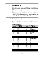
On/off (I/O) information handled by the PROFIBUS unit consists of 16 dedicated in-
puts, 32 general-purpose I/O inputs, 16 dedicated outputs and 32 general-purpose out-
puts.
Dedicated inputs are sub-grouped by assigned function into 13 dedicated command in-
puts, interlock, service mode and emergency stop inputs.
* Some ports are currently reserved for future use and not available for dedicated com-
mand input and dedicated outputs.
* PROFIBUS I/O functions and methods for using them are basically identical to those
for the parallel I/O that are a standard feature in the controller.
2-7-1
Profile (I/O signal table)
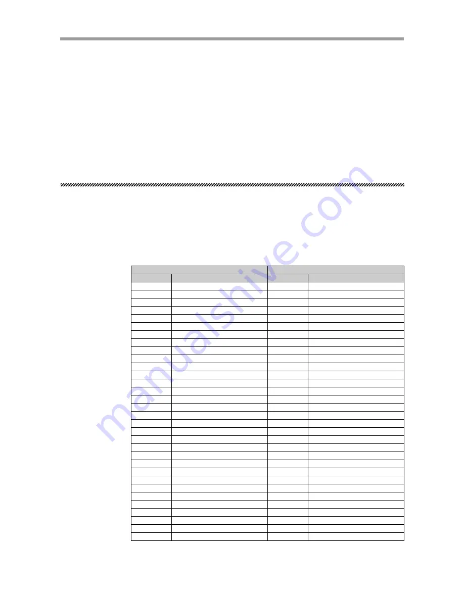
The following table is a list profiling the PROFIBUS unit.
More detailed information on each signal is listed in “2-7-2 Dedicated command in-
puts”.
Remote I/O signals (Bit I/O)
Servo status (SRV-O)
(ZONE 0)
(ZONE 1)
(ZONE 2)
(ZONE 3)
Reserved
Origin return status (ORG-O)
Reserved
Reserved
Reserved
Reserved
Reserved
Reserved
END
BUSY (executing command)
READY
SO200
SO201
SO202
SO203
SO204
SO205
SO206
SO207
SO208
SO209
SO210
SO211
SO212
SO213
SO214
SO215
Im.0
Im.1
Im.2
Im.3
Im.4
Im.5
Im.6
Im.7
Im+1.0
Im+1.1
Im+1.2
Im+1.3
Im+1.4
Im+1.5
Im+1.6
Im+1.7
Im+2.0
Im+2.1
Im+2.2
Im+2.3
Im+2.4
Im+2.5
Im+2.6
Im+2.7
Im+3.0
Im+3.1
Im+3.2
Im+3.3
Im+3.4
Im+3.5
Im+3.6
Im+3.7
SERVO (servo recovery)
INC-PT (move relative point)
ABS-PT (move absolute point)
STEP-R (step operation)
AUTO-R (auto operation)
RESET
ORG-S (origin return)
LOCK (interlock)
Reserved
Reserved
Reserved
Reserved
Reserved
Reserved
SVCE (service mode)
EMG (emergency stop input)
SI200
SI201
SI202
SI203
SI204
SI205
SI206
SI207
SI208
SI209
SI210
SI211
SI212
SI213
SI214
SI215
Qn.0
Qn.1
Qn.2
Qn.3
Qn.4
Qn.5
Qn.6
Qn.7
Qn+1.0
Qn+1.1
Qn+1.2
Qn+1.3
Qn+1.4
Qn+1.5
Qn+1.6
Qn+1.7
Qn+2.0
Qn+2.1
Qn+2.2
Qn+2.3
Qn+2.4
Qn+2.5
Qn+2.6
Qn+2.7
Qn+3.0
Qn+3.1
Qn+3.2
Qn+3.3
Qn+3.4
Qn+3.5
Qn+3.6
Qn+3.7
OUTPUT (Slave
→
Master)
INPUT (Master
→
Slave)
Address
Signal Name
Address
Signal Name


