background image

4-

58

Operation

4

10. “PROGRAM” mode

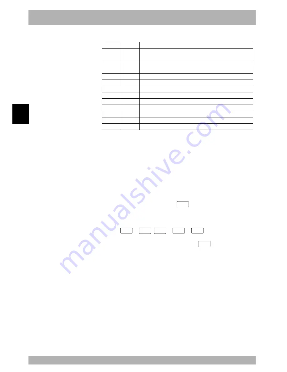
Valid keys and submenu descriptions in “PROGRAM >DIR” mode are shown below.

Valid keys

Cursor key

 (

/

)

Cursor key

 (

←/→

)

Page key

F1

F5

F6

F7

F8

F10

F11

F15

Menu

NEW

INFO

COPY

ERASE

RENAME

ATTRBT

OBJECT

EXAMPLE

Function

Selects the program or scrolls the screen vertically.

Switches between the program information display and the date/time display.

Switches to other screens.

Registers a new program name.

Shows the number of bytes used for the entire program.

Copies the program.

Erases the program.

Renames the program.

Changes the program attribute.

Shows the object program information.

Automatically creates the program name "FUNCTION".

10.3.1

Cursor movement

[Procedure]

To select the program, use the cursor (

/

) keys in “PROGRAM>DIR” mode.

The pointer cursor moves to the selected program number.
The program name is displayed at the right end on the system line (1st line).

10.3.2

Registering a new program name

When creating a new program, you must first register the program name.

[Procedure]

1) In “PROGRAM>DIR” mode, press the 

F  1

 (NEW) key to enter

“PROGRAM>DIR>NEW” mode.
The message “Enter program name > “ appears on the guideline.

2) Use the 

0

 to 

9

A

 to 

Z

 or 

_

 keys to enter a program

name.

A maximum of 8 characters can be used. (Press the 

ESC

 key if you want to

cancel the data input.)

Содержание RCX40

Страница 1: ...User s Manual ENGLISH E YAMAHA 4 AXIS ROBOT CONTROLLER E75 Ver 12 00 RCX40 ...

Страница 2: ......

Страница 3: ...anual explains how to install and operate the robot controller Be sure to read this manual carefully as well as related manuals and comply with their instructions for using the YAMAHA robot controllers safely and correctly For details on robot programs refer to the separate Programming Manual ...

Страница 4: ...ath to the operator bystanders or persons inspecting or repairing the robot controller or robot c CAUTION Failure to follow CAUTION instructions may result in injury to the operator bystanders or persons inspecting or repairing the robot controller or robot and may damage the robot controller or robot n NOTE Explains the key point in the operation in a simple and clear manner Note that the items c...

Страница 5: ...nnections Never directly touch the conductive sections or electronic parts other than the rotary switches and DIP switches on the outside panel of the robot controller Securely install each connection cable connector into the receptacles or sockets Poor connections will cause faulty operation or malfunctions Wiring safety points w WARNING Always shut off all phases of the power supply externally b...

Страница 6: ...or fire Always shut off all phases of the power supply externally before installing or removing an option board Failure to shut off all phases could lead to breakdowns or malfunctions When using ferrite cores for noise elimination fit them to the power cable as close to the robot controller as possible to prevent faulty operation or malfunctions due to noise When performing maintenance of the robo...

Страница 7: ... the absolute battery in Chapter 3 before connecting the robot cables An error relating to absolute settings is always issued if the robot controller power is turned on without making the absolute battery connections so the origin position is not detected This means the robot connected to this controller cannot be used as absolute specifications 3 When connecting robot cables to the robot controll...

Страница 8: ...ograms 1 Standard Language for Industrial Manipulators 2 This compiling method checks the syntax in a robot language program converts it into intermediate codes and creates an execution file object file before actually performing the program 3 Movement command Arch motion Spatial movement during pick and place work can be freely set according to the work environment This is effective in reducing c...

Страница 9: ...m 2 5 3 1 Basic configuration 2 5 4 Optional devices 2 6 4 1 MPB programming device 2 6 4 2 Expansion I O board 2 6 4 3 Regenerative unit 2 6 Chapter 3 Installation 1 Unpacking 3 1 1 1 Packing box 3 1 1 2 Unpacking 3 1 2 Installing the robot controller 3 2 2 1 Installation 3 2 2 2 Installation methods 3 3 3 Connectors 3 5 4 Power connections 3 6 4 1 AC200 to 230V single phase specifications 3 6 4 ...

Страница 10: ...nctions 4 2 3 MPB programming unit 4 3 3 1 Part names 4 3 3 2 Main functions 4 4 3 3 Connection to the robot controller 4 5 4 Turning power on and off 4 6 5 Operation keys 4 7 5 1 MPB screen 4 7 5 2 Operation key layout 4 8 5 3 Basic key operation 4 9 5 4 Function keys 4 10 5 5 Control keys 4 12 5 6 Data keys 4 14 5 7 Other keys 4 14 6 Emergency stop 4 15 6 1 Emergency stop reset 4 16 7 Mode confi...

Страница 11: ...Copying the selected lines 4 53 10 2 10 Cutting the selected lines 4 54 10 2 11 Pasting the data 4 54 10 2 12 Backspace 4 54 10 2 13 Line jump 4 55 10 2 14 Searching a character string 4 56 10 3 Directory 4 57 10 3 1 Cursor movement 4 58 10 3 2 Registering a new program name 4 58 10 3 3 Directory information display 4 59 10 3 4 Copying a program 4 60 10 3 5 Erasing a program 4 61 10 3 6 Renaming a...

Страница 12: ...ft coordinate setting method 1 4 109 11 5 4 Shift coordinate setting method 2 4 111 11 6 Displaying editing and setting hand definitions 4 113 11 6 1 Editing hand definitions 4 119 11 6 1 1 Restoring hand definitions 4 120 11 6 2 Hand definition setting method 1 4 120 11 7 Changing the display units 4 122 11 8 Absolute reset 4 123 11 8 1 Checking absolute reset 4 124 11 8 2 Axis absolute reset 4 1...

Страница 13: ... the execution level 4 219 14 5 2 Displaying the Help message 4 220 14 6 Changing the access level operation level 4 221 14 6 1 Entering the password 4 221 14 6 2 Changing the access level 4 222 14 6 3 Displaying the Help message 4 222 Chapter 5 I O interface 1 I O interface overview 5 1 1 1 Power supply 5 1 1 2 Connector I O signals 5 2 1 3 Connector pin numbers 5 3 1 4 Typical I O signal connect...

Страница 14: ...cription 6 7 Chapter 7 RS 232C interface 1 Communication overview 7 1 2 Communication function overview 7 2 3 Communication specifications 7 3 3 1 Connector 7 3 3 2 Transmission mode and communication parameters 7 4 3 3 Communication flow control 7 5 3 3 1 Flow control during transmit 7 5 3 3 2 Flow control during receive 7 5 3 4 Other caution items 7 6 3 5 Character code table 7 7 Chapter 8 Speci...

Страница 15: ...26 13 MPB errors 9 29 14 RS 232C communication errors 9 30 15 Memory card errors 9 31 17 Motor control errors 9 34 21 Major software errors 9 40 22 Major hardware errors 9 42 1 2 MPB Error Messages 9 45 2 Troubleshooting 9 47 2 1 When trouble occurs 9 47 2 2 Acquiring error information 9 48 2 2 1 Acquiring information from the MPB 9 48 2 2 2 Acquiring information from the RS 232C 9 48 2 3 Troubles...

Страница 16: ...viii MEMO ...

Страница 17: ...fety 1 1 1 1 Safety precautions during robot operation 1 2 1 2 Safety precautions during maintenance 1 2 1 3 Precautions for motor overload 1 2 1 4 Warning labels 1 3 1 5 Warning marks 1 3 2 Warranty 1 4 3 Operating environment 1 5 ...

Страница 18: ...MEMO ...

Страница 19: ...entified in this manual by the following symbols w WARNING Failure to follow WARNING instructions could result in severe injury or death to the operator bystanders or persons inspecting or repairing the robot controller or robot c CAUTION Failure to follow CAUTION instructions may result in injury to the operator bystanders or persons inspecting or repairing the robot controller or robot and may d...

Страница 20: ...obot or controller In cases where you have to replace or repair parts used in the robot or controller first consult with us and follow the instructions we provide b Before beginning maintenance for the robot or controller be sure to turn off the power to the controller Even after turning off the controller there are some parts in the controller which are still hot or at a high voltage Always wait ...

Страница 21: ...oller read this manual carefully and follow the instructions Connectors have an orientation so insert each connector in the correct direction 1 5 Warning marks The following warning marks are shown on the controller To use the YAMAHA robot and controller safely and correctly be sure to observe the instructions and caution of the marks a Electric Hazard mark This mark warns you of possible electric...

Страница 22: ...d other internal data that were changed or created by the ser Failures resulting from the following causes are not covered by warranty repair 1 Damage due to earthquakes storms floods thunderbolt fire or any other natural or man made disasters 2 Troubles caused by procedures prohibited in this manual 3 Modifications to the robot and or related product not approved by YAMAHA or YAMAHA sales represe...

Страница 23: ...humidity The ambient humidity of the robot controller should be 35 to 85 RH no condensation in order to guarantee continuous operation within the initial specifications Installing the robot controller inside an air conditioned or cooled housing is recommended when an ambient humidity is higher than 85 or condensation occurs Storage humidity The controller should be stored in a location at an ambie...

Страница 24: ...1 6 MEMO ...

Страница 25: ...ation 2 1 1 2 Axis definition for the RCX40 2 3 2 Part names and functions 2 4 2 1 RCX40 Maximum number of axes 4 axes 2 4 3 Controller system 2 5 3 1 Basic configuration 2 5 4 Optional devices 2 6 4 1 MPB programming device 2 6 4 2 Expansion I O board 2 6 4 3 Regenerative unit 2 6 ...

Страница 26: ...MEMO ...

Страница 27: ...tions Applications also include various inspection instruments sealers and spray equipment utilizing linear and circular interpolation functions 1 1 Main system configuration Configuration 1 System for controlling one robot Example YK400X All the axes on the robot controller are used as the main robot axes Fig 2 1 1 System for controlling one robot PC PLC MPB YAMAHA robot ...

Страница 28: ... controlling one robot and auxiliary axes Example SXYx T9 T9 Axes 1 and 2 on the robot controller are used as the main robot axes and axes 3 and 4 are used as the main auxiliary axes Fig 2 1 2 System for controlling one robot and auxiliary axes PLC MPB PC YAMAHA robot ...

Страница 29: ... The letters M are displayed on the MPB 1 to 4 Main auxiliary axes Are the single axes composing the main group These cannot be moved with the robot language MOVE command Use the DRIVE command to move these axes The letters m are displayed on the MPB 1 to 4 Sub group Indicates the sub robot and sub auxiliary axes and has a maximum of 2 axes The letters SG are displayed on the MPB Sub robot Indicat...

Страница 30: ...rview 2 2 Part names and functions 2 1 RCX40 Maximum number of axes 4 axes Fig 2 2 1 RCX40 MOTOR XM YM ZM RM PWR SRV ERR SAFETY MPB COM STD DIO BATT RGEN ACIN X Y Z R P N L N ROB I O XY ROB I O ZR OP 1 OP 3 OP 2 OP 4 ...

Страница 31: ...1 CN2 CN2 CN1 CN6 CN2 CN1 CN3 HEATSINK CN4 CN6 CN7 CN3 CN10 CN7 CN2 TB1 CN4 CN1 CN1 CN2 CN1 CN2 CN6 CN8 CN9 CN11 CN5 TH1 FG CN11 CN13 CN4 CN8 CN12 CN10 CN8 CN3 CN1 CN3 CN3 CN3 CN3 YM ZM RM ROB I O XY ROB I O ZR COM SAFETY MPB STD DIO D POWER BOARD ASSY DRIVER2 BOARD ASSY DRIVER1 BOARD ASSY CPU BOARD ASSY OP BOARD OP BOARD OP BOARD OP BOARD X Y Z R BATT ACIN POWER CPU UNIT1 AC DC 24V POWER CPU UNIT...

Страница 32: ...ing and parameter settings Fig 2 4 1 Emergency stop button 4 2 Expansion I O board A standard I O board used in the robot controller has 24 general purpose input points and 16 general purpose output points A maximum of 4 expansion I O boards can be installed to increase the input output points 4 3 Regenerative unit A regenerative unit may be required depending on the robot type or application ...

Страница 33: ...trol switch installation 3 8 5 Robot cable connections 3 9 6 Connecting the MPB programming unit 3 10 7 I O connections 3 11 8 Connecting a host computer 3 12 9 Connecting the absolute battery 3 13 10 Replacing the absolute battery 3 15 11 Connecting a regenerative unit 3 18 12 Precautions for cable routing and installation 3 19 12 1 Wiring methods 3 19 12 2 Precautions for installation 3 19 12 3 ...

Страница 34: ...MEMO ...

Страница 35: ... apply shocks to the equipment when unpacking After unpacking check the accessories to make sure that nothing is missing Fig 3 1 1 Unpacking Accessories MPB Standard Option Accessories 1 1 1 1 1 1 1 2 4 Max 4 Max 1 STD DIO connector MPB terminator L type bracket set for front and rear panels SAFETY connector Connector guard for COM connector CD ROM manual MPB programming unit L type brackets for s...

Страница 36: ...amage 2 Take care not to allow the connectors on the front of the robot controller to be hit or bumped Shocks received by the connectors may damage the PC boards in the controller 3 Be sure to give the cables used to connect the controller enough extra length to avoid strain and pulling at the connectors 4 Keep the controller away from oil and water If the controller is to be used under such adver...

Страница 37: ...ontroller as explained below 1 Using the rubber feet attached as standard parts Fig 3 2 2 1 2 Attaching the L type brackets supplied as standard accessories to the front Fig 3 2 2 2 c CAUTION When the L type brackets have mounting holes in two different positions use the holes that are more suitable for the equipment layout ...

Страница 38: ...hing the L type brackets option to the side Fig 3 2 2 4 c CAUTION When attaching the L type brackets to the rear of the controller provide a clearance of at least 30mm between the rear panel and wall or other objects When the L type brackets have mounting holes in two different positions use the holes that are more suitable for the equipment layout ...

Страница 39: ...Y Z R REGN P N AC IN L N Connectors for servomotor drive Connectors for servomotor feedback and sensor signals Input output connector for safety function such as emergency stop Connector for MPB RS 232C interface connector Connector for dedicated input output and standard general purpose input output Connectors attached to optional expansion I O boards Battery connector for absolute backup Connect...

Страница 40: ...artesian robot or multi axis robot Axis current sensor value X axis 05 10 20 10 20 20 Y axis 05 05 05 10 10 20 Power capacity VA 600 800 1100 1000 1300 1700 c CAUTION Before connecting the power cable be sure to check that the power supply voltage matches the power specifications of your controller c CAUTION The power supply voltage for the robot controller must always be regulated within 10 If th...

Страница 41: ...300 1600 1200 1500 1800 2000 4 When connected to 4 axes Cartesian robot and or multi axis robot Axis current sensor value X axis 05 10 20 10 20 20 10 20 20 20 10 20 20 20 20 Y axis 05 05 05 10 10 20 10 10 20 20 10 10 20 20 20 Z axis 05 05 05 05 05 05 10 10 10 20 10 10 10 20 20 R axis 05 05 05 05 05 05 05 05 05 05 10 10 10 10 20 Power capacity VA 800 1000 1200 1100 1400 1600 1300 1500 1800 2100 140...

Страница 42: ...r to the circuit protector manufacturer s data sheets for making the selection Example RCX40 20A Rated current Operating characteristics Slow type with inertia delay 300 2 sec 1000 0 01 sec 4 5 Current control switch installation When controlling the power on off of the robot controller from an external device such as a PLC a current control switch contactor breaker etc may be used In this case an...

Страница 43: ... off when connecting the robot cables The robot cable connectors XM and YM ZM and RM ROB I O XY and ROB I O ZR have an identical shape Do not confuse these cable connectors when making connections Misconnection will cause the robot to malfunction Keep robot cables separate from the robot controller power connection lines and other equipment power lines Using in close contact with lines carrying po...

Страница 44: ...connection MPB programming unit c CAUTION Use caution since the MPB connector must be connected in the correct direction Connecting in the wrong direction may cause faulty operation or breakdowns Emergency stop in the robot controller is triggered when the MPB is disconnected from the robot controller because a B contact type emergency stop button is provided on the MPB So be sure to plug the MPB ...

Страница 45: ...lector transistor is used for the I O port having a transistor and photocoupler and a corresponding DI digital input is also used NPN specifications therefore make use of a sink output and a source input see drawing below Current Current DO output sink type DI input source type N COM P COM NPN b PNP specifications PNP specifications indicate that a DO digital output type PNP open collector transis...

Страница 46: ...ng between the COM connector on the front of the robot controller and the RS 232C port of the computer For more detailed information on the RS 232C interface see RS 232C Interface in Chapter 7 Fig 3 8 1 Host computer connection RCX40 MOTOR XM YM ZM RM PWR SRV ERR SAFETY MPB COM STD DIO BATT RGEN ACIN X Y Z R P N L N ROB I O XY ROB I O ZR OP 1 OP 3 OP 2 OP 4 Host computer COM connector D SUB 9P fem...

Страница 47: ...robot cable Connecting the absolute battery For controller equipped with B3 battery 1 Connect the absolute battery connectors to the BATT X Y Z and R connectors on the front right of the controller as shown below Fig 3 9 1 R Z Y X R Z Y X For controller equipped with regenerative unit 1 Pass the absolute battery cords along the groove of the stay so that they come out of the front of the controlle...

Страница 48: ... time or the backup time was exceeded while the controller power was off The battery is automatically charged when power is supplied to the controller Keep power supplied for longer than needed to charge the battery by referring to the table below Battery type 3 6V 2000mAh KS4 M53G0 100 3 6V 4000mAh KS4 M53G0 200 Battery name 1 B3 B4 Hours until full charge 2 48h 96h Backup time 3 340h 680h 1 YAMA...

Страница 49: ...ower is off with the absolute battery fully charged Replacing the absolute battery When the RGU 2 is mounted remove the four screws on the top and bottom with a Phillips screwdriver and remove the RGU 2 a For B3 battery 1 Unfasten the tie strap on the battery holder 2 Unplug the connector for the absolute battery to be replaced and then remove the absolute battery by pulling it towards you as seen...

Страница 50: ...sing a Phillips screwdriver remove the four screws on the upper and lower stays coupling the two battery holders The battery holder is not coupled if the RGU 2 is not mounted Fig 3 10 3 Screws Screws Battery holders Stays Fig 3 10 4 For X axis For Z axis For Y axis For R axis ...

Страница 51: ...ry to be replaced and then remove the absolute battery by pulling it toward you Fig 3 10 5 2 1 4 Insert the new absolute battery slowly into the battery holder After inserting check that the battery is securely installed in position by the holder hook Fig 3 10 6 1 2 5 Fasten the absolute battery cord with the tie strap band at the center of the battery holder ...

Страница 52: ...h the regenerative unit Fig 3 11 Connector RGEN w WARNING The power to the controller must be off when connecting the generative unit to the robot controller To prevent electrical shocks never touch the RGEN terminals when power is supplied to the robot controller n NOTE Check the cable and connectors for bent pins kinks and other damage before connecting c CAUTION Always securely connect the cabl...

Страница 53: ...s possible 12 2 Precautions for installation This robot controller is not designed for explosion proof dust proof and drip proof con struction Do not install it in the following locations or environment 1 exposed to flammable gases or liquids 2 where conductive debris such as metal cutting chips are spread 3 subject to corrosive gases such as acid gases and alkaline gases 4 exposed to cutting oil ...

Страница 54: ...located near the robot controller Example of surge absorber For inductive motor Single phase motor A 3 phase motor A A Surge killer Okaya Electric Industries CRE 50500 3CRE 50500 or equivalent For solenoid valve solenoid B B Diode varistor CR elements DC type C Varistor CR elements AC type C 12 Precautions for cable routing and installation ...

Страница 55: ...check connections to the following items must be finished Power supply Do not supply power until you actually begin the operation check Robot cable MPB programming unit Absolute battery Regenerative unit if needed SAFETY connector supplied Pin 3 is shorted to pin 13 and pin 4 is shorted to pin 14 in the SAFETY connector 13 1 Cable connection Fig 3 13 1 SAFETY connector supplied MPB YAMAHA robot Ho...

Страница 56: ...SAFETY connector SAFETY connector supplied RCX40 AC 200V Motor power supply relay coil Motor power supply circuit The emergency stop button on the MPB is connected to the controller through the SAFETY connector 13 3 Operation check After connecting the robot and special connector supplied to the controller turn on the power to the controller and check the following points Normal operation The PWR ...

Страница 57: ...7 5 1 MPB screen 4 7 5 2 Operation key layout 4 8 5 3 Basic key operation 4 9 5 4 Function keys 4 10 5 5 Control keys 4 12 5 6 Data keys 4 14 5 7 Other keys 4 14 6 Emergency stop 4 15 6 1 Emergency stop reset 4 16 7 Mode configuration 4 18 7 1 Basic operation modes 4 18 7 2 Other operation modes 4 19 7 3 Mode hierarchy 4 20 8 SERVICE mode 4 24 8 1 Operation device 4 24 8 2 Prohibition of AUTO mode...

Страница 58: ... Deleting a character 4 51 10 2 5 Deleting a line 4 52 10 2 6 User function key display 4 52 10 2 7 Quitting program editing 4 53 10 2 8 Specifying the copy cut lines 4 53 10 2 9 Copying the selected lines 4 53 10 2 10 Cutting the selected lines 4 54 10 2 11 Pasting the data 4 54 10 2 12 Backspace 4 54 10 2 13 Line jump 4 55 10 2 14 Searching a character string 4 56 10 3 Directory 4 57 10 3 1 Curs...

Страница 59: ...nition 4 101 11 4 Changing the manual movement speed 4 102 11 5 Displaying editing and setting shift coordinates 4 103 11 5 1 Editing shift coordinates 4 106 11 5 1 1 Restoring shift coordinates 4 107 11 5 2 Editing the shift coordinate range 4 107 11 5 2 1 Restoring a shift coordinate range 4 109 11 5 3 Shift coordinate setting method 1 4 109 11 5 4 Shift coordinate setting method 2 4 111 11 6 Di...

Страница 60: ...y 4 206 12 5 4 System error details display 4 206 12 6 Backup processes 4 207 12 6 1 Internal flash ROM 4 207 12 6 1 1 Loading files 4 208 12 6 1 2 Saving files 4 209 12 6 1 3 Initializing the files 4 209 13 MONITOR mode 4 210 14 UTILITY mode 4 212 14 1 Canceling emergency stop Motor power and servo on off 4 213 14 1 1 Canceling emergency stop 4 213 14 1 2 Motor power and servo on off 4 214 14 2 E...

Страница 61: ...roller MPB is used for robot operation programming teaching parameter input etc Used for basic input output operations Used for input output of emergency stop signal enable switch signal etc Used for communication through RS 232C RS 232C interface Controller This chapter mainly explains how to operate the MPB programming unit n NOTE Refer to Chapter 5 for standard I O interface Refer to Chapter 6 ...

Страница 62: ...or 6 COM connector PWR SRV ERR 2 POWER LED 3 SERVO LED 4 ERROR LED 2 2 Main functions q AC IN terminal Supplies power to the controller w PWR LED Lights up when the controller is turned on e SRV LED Lights up when the robot servo is on and turns off when the servo power is off r ERR LED Lights up when a serious error occurs t MPB connector Connects to the MPB programming unit y COM connector Conne...

Страница 63: ...ot controller and allows you to edit or execute robot programs 3 1 Part names Fig 4 3 1 MPB programming unit q Display liquid crystal screen e Emergency stop button r MPB connector w Sheet key u Display contrast adjustment trimmer side of MPB y LOWER button t UPPER button ...

Страница 64: ...s e Emergency stop button Pressing this button during operation immediately stops the robot operation This is a B contact type switch r MPB connector Use this connector to connect the MPB to the robot controller t UPPER button This button has the same function as the UPPER sheet key y LOWER button This button has the same function as the LOWER sheet key u LCD contrast adjustment trimmer side of MP...

Страница 65: ...owns Fig 4 3 2 Robot controller connection RCX40 MOTOR XM YM ZM RM PWR SRV ERR SAFETY MPB COM STD DIO BATT RGEN ACIN X Y Z R P N L N ROB I O XY ROB I O ZR OP 1 OP 3 OP 2 OP 4 MPB connector MPB programming unit 3 MPB programming unit n NOTE Emergency stop is triggered when the MPB is connected to or disconnected from the robot controller while the power is on If this happens emergency stop must be ...

Страница 66: ...een MANUAL 50 MR S0H0J Current position M1 0 M4 0 M2 0 M3 0 POINT PALLET VEL VEL c CAUTION When connecting the MPB to the robot controller always use the dedicated cable and connector attached to the MBP Do not modify this cable or extend it by using a relay unit etc n NOTE If an error message Parameter destroyed or Memory destroyed appears on the screen when the robot controller is turned on be s...

Страница 67: ...rn to origin complete Program is being executed Online command is being executed through RS 232C interface Changes to a dot when the command ends Sequence program is being executed 3 Data area 3rd to 7th lines Various types of data and editing information are displayed on the 3rd to 7th lines These lines scroll to the right and left to show up to 80 characters per line 4 Guideline Bottom line The ...

Страница 68: ...eys 5 2 Operation key layout The operation keys are covered with a plastic sheet to prevent dust There are 3 main kinds of keys 1 Function keys 2 Control keys 3 Data keys Fig 4 5 2 Sheet key layout Control key Functin key Data key ...

Страница 69: ...nable various functions Fig 4 5 3 Key configuration Shift 1 Shift 2 Shift 3 2 There are 3 ways shift 1 to shift 3 to use each operation key Shift 1 2 3 Example of key input Shift 1 Use a key while holding down the key Input data UPPER UPPER LOWER LOWER LOWER Shift 3 Use a key while holding down the key Shift 2 Use a key without holding down the and keys UPPER ...

Страница 70: ...their menus in MANUAL mode is shown below Function key Selected menu POINT PALLET VEL VEL SHIFT HAND UNITCHG VEL VEL ABS RST COORDI F 1 F 2 F 4 F 5 F 6 F 7 F 8 F 9 F10 F13 F15 UPPER UPPER UPPER UPPER UPPER LOWER LOWER F 1 F 6 F 11 F 2 F 7 F 12 F 1 F 6 F 11 F 2 F 7 F 12 F 3 F 8 F 13 F 4 F 9 F 14 F 4 F 9 F 14 F 5 F 10 F 15 F 5 F 10 F 15 F 3 F 8 F 13 F 5 F 10 F 15 ...

Страница 71: ...e MPB correspond to the function key menus on the screen from the left Pressing the UPPER key switches to function keys F 6 to F 10 and pressing the LOWER key switches to function keys F 11 to F 15 n NOTE From hereon when the F 6 to F 10 keys are mentioned it means to press the F 1 F6 F11 to F 5 F10 F15 keys while holding down the UPPER key or UPPER button on the side Likewise when the F 11 to F 1...

Страница 72: ... the previous screen upper hierarchy 3 Cursor keys Moves the cursor up Moves the pointer highlighted line number display up when not editing on the screen Moves the cursor down Moves the pointer highlighted line number display down when not editing on the screen Moves the cursor to the left Screen scrolls to the right when the cursor reaches the left end Scrolls the screen to the right when not ed...

Страница 73: ...lid during program execution direct command execution point trace execution and return to origin operation 1 Moves axis 1 in the direction or the robot in the X direction on the XY coordinates 1 Moves axis 1 in the direction or the robot in the X direction on the XY coordinates 2 Moves axis 2 in the direction or the robot in the Y direction on the XY coordinates 2 Moves axis 2 in the direction or ...

Страница 74: ...f data keys 1 Alphanumeric keys 0 to 9 Enters numbers A to Z Enters alphabetic characters SPACE Inserts spaces 2 Symbol keys 5 7 Other keys 1 Enter key Pressing this key executes a direct command when in AUTO DIRECT mode When the cursor is displayed pressing this key completes the data input on the cursor line 2 Shift keys UPPER Selects shift 1 for key operation LOWER Selects shift 3 for key opera...

Страница 75: ...ike that shown below appears on the MPB screen The highlighted display for the mode name is cancelled during emergency stop MANUAL 50 MG S0H0J 12 1 Emg stop on Current position POINT PALLET VEL VEL M1 0 M4 0 M2 0 M3 0 Fig 4 6 1 Emergency stop MPB programming unit Emergency stop button n NOTE Besides the emergency stop button on the MPB an external dedicated input emergency stop terminal is provide...

Страница 76: ...r Off Sequence DISABLE Armtype RIGHTY MOTOR SEQUENC ARMTYPE RST DO At this time pressing the ESC key returns to the previous mode with the motor power still turned off To turn on the motor power continue the following operations 4 Press the F 1 MOTOR key The following screen appears Fig 4 6 4 UTILITY MOTOR mode 1 UTILITY MOTOR Motor power Off D1 M1 Brake D5 M5 no axis D2 M2 Brake D6 M6 no axis D3 ...

Страница 77: ... 4 6 5 UTILITY MOTOR mode 2 UTILITY MOTOR Motor power On D1 M1 Servo D5 M5 no axis D2 M2 Servo D6 M6 no axis D3 M3 Servo D4 M4 Servo ON OFF 6 Press the ESC key to return to the previous mode 6 Emergency stop n NOTE If the motor power is turned off due to a serious error the motor power will not turn on by UTILITY MOTOR mode In this case the robot controller must be turned back on again ...

Страница 78: ... to perform maintenance work using the MPB safely within the safety enclosure of the robot system This mode includes AUTO and MANUAL modes in the basic operation mode and can be selected by turning DI02 SERVICE mode OFF The following functions are selected in SERVICE mode Robot is controlled only by MPB operation Automatic operation is prohibited Robot operating speed is set to below 3 of the maxi...

Страница 79: ...and axis parameter settings 7 2 Other operation modes Other than the basic operation modes the following two modes are also available 1 DI DO Monitor mode 2 UTILITY mode These modes can be selected with the control keys 1 DI DO Monitor mode Use this mode to monitor the robot controller I O status or task status on the MPB screen Use the DISPLAY key to select this mode 2 UTILITY mode Use this mode ...

Страница 80: ... menu MANUAL 50 MG S0H0J Current position AUTO PROGRAM MANUAL SYSTEM M1 0 M4 0 M2 0 M3 0 These are basic modes at the highest hierarchy on the menu The display position for each mode name corresponds to each function key of F 1 F 2 F 3 and F 4 from the left For example when the F 1 AUTO key is pressed AUTO mode is entered Fig 4 7 2 AUTO mode menu AUTO T1 100 TEST1 1 TEST1 PROGRAM 2 3 DO2 0 0 4 WAI...

Страница 81: ...roceed through each hierarchy by selecting the menu items with the function keys To return to the previous mode hierarchy press the ESC key Pressing the MODE key directly returns to the highest modes The basic 4 modes are displayed on the guideline so select the desired basic mode by pressing the corresponding function key Refer to Mode hierarchy diagram on the next page for the entire mode hierar...

Страница 82: ...F1 EDIT F2 METHOD F4 VEL F5 VEL F6 COPY F7 ERASE F9 VEL F10 VEL F15 PASSWD F1 EDIT F2 RANGE F4 VEL F5 VEL F6 METHOD1 F7 METHOD2 F9 VEL F10 VEL F2 PROGRAM F1 EDIT F2 TEACH F4 VEL F5 VEL F8 UNITCHG F9 VEL F10 VEL F3 MANUAL F1 RESET F2 TASK F3 DIR F4 VEL F5 VEL F6 POINT F7 DIRECT F8 BREAK F9 VEL F10 VEL F11 STEP F12 SKIP F13 NEXT F1 EDIT F3 DIR F5 COMPILE F6 JUMP F7 FIND F8 FIND F9 FIND F13 ERR RST F...

Страница 83: ... F2 JUMP F1 PARAM F2 CMU F3 OPTION F4 INIT F5 DIAGNOS F9 BACKUP F15 DRV UP F1 PROGRAM F2 POINT F3 SHIFT F4 HAND F5 ALL F6 PALETTE F7 COMMENT F1 DATE F2 TIME F1 ROBOT F2 AXIS F4 CLEAR F5 HELP F6 AUX F7 DUAL F15 LAYOUT F9 DSW HLP F1 EXECUTE F2 ACCESS F5 RST DO F9 DSW HLP UTILITY 1 F1 MOTOR F2 SEQUENC F3 ARMTYPE F5 RST DO UTILITY 2 DISPLAY F1 PARAM F2 MEMORY F3 CMU F4 CLOCK F6 GENERAT F10 PASSWRD F1 ...

Страница 84: ...old to Run function If the robot operator using the MPB should trip or fall during maintenance work he she may be exposed to a dangerous situation To prevent this kind of accident the Hold to Run function allows the robot to move only during the time that the MPB key is kept pressed However the Hold to Run function can be turned OFF provided you take responsibility for your own safety 8 4 Limitati...

Страница 85: ...nt speed r Program name t Message line y Online command execution mark u Sequence program execution mark i Pointer display o Guideline q Mode hierarchy Shows the current mode hierarchy When the highest mode AUTO in this case is not highlighted it means the servomotor power is off When highlighted it means the servomotor power is on w Task display Shows a task number in the program list currently d...

Страница 86: ...UTO mode the specified program is compiled and an object file is created to execute automatic operation When the same object file already exists compiling is not executed If an error is found in a command statement during compiling the error message and the program list after the command line where the error occurred are displayed If the compiling ends normally the program list is displayed from t...

Страница 87: ...ic movement speed for the selected robot group in steps 100 50 20 5 1 Moves to the specified point number position Executes a command statement written on one line Sets a break point Increases automatic movement speed for the selected robot group in 1 increments Decreases automatic movement speed for the selected robot group in 1 decrements Executes one line of the command statement Advances to th...

Страница 88: ...n in progress AUTO T1 100 TEST1 0 2 Running RESET TASK DIR VEL VEL The following keys are enabled during automatic operation ROBOT LOWER MODE Valid keys F9 F10 Menu VEL VEL Function Increases automatic movement speed for the selected robot group in 5 increments Decreases automatic movement speed for the selected robot group in 5 decrements Switches the selected robot group n NOTE Regardless of the...

Страница 89: ...y the program list The pointer indicates the next command line number to be executed in the program 3 Press the START key to re execute the program c CAUTION Do not turn off the robot controller during program execution If turned off an error may occur in the internal system data and the program may not restart normally when the power is again turned on Always be sure to terminate or stop the prog...

Страница 90: ...t exist 1 Press the F 1 RESET key in AUTO mode 2 Press the F 4 YES key A list of the current program appears from the first line A pointer also appears on the first line number of the program Fig 4 9 6 Program reset AUTO T1 50 TEST1 1 ST 2 MOVE P P0 3 MOVE P P1 4 MOVE P P2 5 GOTO ST Reset program OK YES NO n NOTE The output is also reset when the program is reset However the output will not be res...

Страница 91: ... MOVE P P1 4 MOVE P P2 5 GOTO ST Change to _SELECT OK YES NO 2 When the F 5 NO key is pressed in Step 1 the following message then appears on the guideline Press the F 4 YES key to reset the current program or press the F 5 NO key to cancel the reset Fig 4 9 8 Program reset AUTO T1 50 TEST1 1 ST 2 MOVE P P0 3 MOVE P P1 4 MOVE P P2 5 GOTO ST Reset program OK YES NO n NOTE The output is also reset w...

Страница 92: ...executed in the current task Fig 4 9 9 Main task T1 display AUTO T1 100 TEST1 5 MOVE P P0 6 L1 7 MOVE P P1 8 MOVE P P2 9 GOTO L1 RESET TASK DIR VEL VEL 3 Press the F 2 TASK key to select a lower order task program Each time the F 2 TASK key is pressed lower order task programs T2 T3 T8 are displayed At this time the pointer indicates the next command line number to be executed in each task Fig 4 9...

Страница 93: ...ed 2 Use the cursor keys to select the desired program and press the ESC key The selected program will automatically be compiled and an object program file made Fig 4 9 11 Switching programs AUTO DIR T1 100 TEST2 No NAME LINE BYTE RW RO 1 TEST1 13 125 RW 2 TEST2 50 608 RW 3 PARTS100 38 411 RW 4 TEST3 7 78 RW n NOTE The output is also reset when the program is reset However the output will not be r...

Страница 94: ...45 14 P4 96 65 224 89 43 31 28 79 P5 63432 19735 6243 22642 COMNT LEFTY POS 0 0 0 0 PTP JUMP VEL VEL The RIGHTY message on the first line appears only when a SCARA robot is selected The LEFTY message on the sixth line appears only when a SCARA robot is selected and a hand system flag is set for the point data n NOTE When two robots are specified two speeds are displayed for main group sub group Th...

Страница 95: ... group in steps 100 50 20 5 1 Moves the arch axis to the right during ARCH motion mode Moves the arch axis to the left during ARCH motion mode Switches the units for indicating the current position to mm pulse Increases automatic movement speed for the selected robot group in 1 increments Decreases automatic movement speed for the selected robot group in 1 decrements Switches to the point data edi...

Страница 96: ...motion mode with no auxiliary axis AUTO POINT RIGHTY 50 100 MG S0H0J x y z r P3 150 50 64 53 21 78 45 14 P4 96 65 224 89 43 31 28 79 P5 63432 19735 6243 22642 COMNT LEFTY POS 0 0 0 0 PTP JUMP VEL VEL 3 Press the START key and the robot moves by PTP motion to the specified point position The trace speed is one tenth of the automatic movement speed If the SCARA robot is selected and the hand system ...

Страница 97: ... 89 43 31 28 79 P5 63432 19735 6243 22642 COMNT LEFTY POS 0 0 0 0 PTP JUMP VEL VEL To perform trace for the auxiliary axis Fig 4 9 17 Point trace screen in PTP motion mode with auxiliary axis AUTO POINT RIGHTY 50 100 MG S0H0J x y z r P3 150 50 64 53 21 78 45 14 P4 96 65 224 89 43 31 28 79 P5 63432 19735 6243 22642 COMNT LEFTY POS 0 0 0 0 PTP JUMP VEL VEL 3 Press the START key and the robot moves b...

Страница 98: ...OMNT LEFTY POS 0 0 0 0 ARCH A POS JUMD VEL VEL 3 Press the F 2 A POS key and set the arch motion position Fig 4 9 20 Point trace screen in ARCH motion mode with no auxiliary axis AUTO POINT RIGHTY 50 100 MG S0H0J x y ARCH z r P3 150 50 64 53 21 78 45 14 P4 96 65 224 89 43 31 28 79 P5 63432 19735 6243 22642 COMNT LEFTY POS 0 0 0 0 Enter ARCH data 20000 4 Use the cursor keys to select the point numb...

Страница 99: ...3 Press the F 2 A POS key and set the arch motion position Fig 4 9 23 Point trace screen in ARCH motion mode with auxiliary axis AUTO POINT RIGHTY 50 100 MG S0H0J x y z r P3 150 50 64 53 21 78 45 14 P4 96 65 224 89 43 31 28 79 P5 63432 19735 6243 22642 COMNT LEFTY POS 0 0 0 0 Enter ARCH data 20000 4 Use the cursor keys and F 14 AXIS or F 15 AXIS key so that the point value of the robot axis to be ...

Страница 100: ...y axis AUTO POINT RIGHTY 50 100 MG S0H0J x y z r P3 150 50 64 53 21 78 45 14 P4 96 65 224 89 43 31 28 79 P5 63432 19735 6243 22642 COMNT LEFTY POS 0 0 0 0 LINEAR JUMP VEL VEL 3 Press the START key to move the robot by linear interpolation motion to the specified point position The trace speed is one tenth of the automatic movement speed If the SCARA robot is selected and the hand system flag is se...

Страница 101: ... LEFTY POS 0 0 0 0 LINEAR JUMP VEL VEL To perform trace for the auxiliary axis Fig 4 9 28 Point trace screen in linear interpolation motion mode with auxiliary axis AUTO POINT RIGHTY 50 100 MG S0H0J x y z r P3 150 50 64 53 21 78 45 14 P4 96 65 224 89 43 31 28 79 P5 63432 19735 6243 22642 COMNT LEFTY POS 0 0 0 0 LINEAR JUMP VEL VEL 3 Press the START key to move the robot by linear interpolation mot...

Страница 102: ...mmand execution AUTO T1 100 TEST1 1 TEST1 PROGRAM 2 START SUBTASK T2 3 DO2 0 0 4 WAIT DI3 4 3 2 3 5 MOVE P P0 DO 25 1_ 2 Enter one line of the command statement 3 Press the key to execute the command you have just entered n NOTE The following command statements can be executed directly Assignment statements movement commands SET statements RESET statements etc Before executing a movement command r...

Страница 103: ...t Searches for the line set with the break point Shows the program list from specified line Specifies the character string to be found Finds the specified character string searching backwards from the cursor position Finds the specified character string searching forwards from the cursor position 9 9 1 Break point setting To make program debugging easy the program execution can be stopped on the l...

Страница 104: ...ress the F 2 CANCEL key The B mark disappears and the break point is canceled 3 To find the line number on which another break point was set press the F 3 SEARCH key This function makes it easier to find a break point you want to delete n NOTE Up to 4 break points can be set in one program These 4 break points cannot set in different programs However when there is COMMON program 4 break points can...

Страница 105: ...hout executing the command statement of the line number where the pointer is displayed 9 12 NEXT Procedure 1 Press the F 13 NEXT key in AUTO mode 2 Each time this key is pressed the command statement of the highlighted line number is executed After execution the pointer moves to the next line If the command statement is a sub routine or sub procedure it is executed at one time w WARNING The robot ...

Страница 106: ...en the highest mode PROGRAM in this case is highlighted it means the servomotor power is on When not highlighted it means the servomotor power is off w Program name Shows the program name currently selected e Message line This line shows the number of digits of the program If an error occurs the error message also appears here r Online command execution mark When an online command is being execute...

Страница 107: ...pecified character string searching backwards from the cursor position Finds the specified character string searching forwards from the cursor position Allows editing if the selected program is destroyed 10 1 Program list scroll Procedure 1 Pressing the cursor keys in PROGRAM mode scrolls up or down through a program list one line at a time Pressing the cursor keys scrolls right or left through a ...

Страница 108: ... Fig 4 10 2 PROGRAM EDIT mode PROGRAM EDIT TEST2 1 TEST2 PROGRAM 2 GOSUB SUBPROG 3 DO2 0 0 4 WAIT DI3 4 3 2 3 5 MOVE P P0 ORIGIN SELECT COPY CUT PASTE BS 1 2 3 Pressing the key finishes the program input for one line and moves the cursor to the beginning of the next line 3 When program editing is complete press the ESC key n NOTE Program editing is finished when any of the key up down cursor keys ...

Страница 109: ...ey Ends program editing Finishes the program input for one line and moves the cursor to the beginning of the next line Selects the starting line for copy or cut Copies the selected line and temporarily stores it in a buffer Cuts the selected lines and temporarily stores it in a buffer Inserts the buffer data directly prior to the cursor line Backs the cursor and deletes the preceding character Dis...

Страница 110: ...rsor movement PROGRAM EDIT TEST2 3 DO2 0 0 4 WAIT DI3 4 3 2 3 5 MOVE P P0_ ORIGIN 6 MOVE P P1 7 DO2 1 1 SELECT COPY CUT PASTE BS 1 2 3 10 2 2 Insert Overwrite mode switching Procedure 1 Press the INS key in PROGRAM EDIT mode The cursor changes to underline _ form and the screen switches to Insert mode In Insert mode the input character is inserted just previous to the cursor position Fig 4 10 4 In...

Страница 111: ... 3 2 3 5 MOVE P P0 ORIGIN 6 MOVE P P1 7 SELECT COPY CUT PASTE BS 1 2 3 10 2 3 Inserting a line Procedure Pressing the L INS LOWER INS key in PROGRAM EDIT mode inserts a blank line at the line previous to the cursor position Fig 4 10 6 Inserting a line PROGRAM EDIT TEST2 3 DO2 0 0 4 WAIT DI3 4 3 2 3 5 _ 6 MOVE P P0 ORIGIN 7 MOVE P P1 SELECT COPY CUT PASTE BS 1 2 3 10 2 4 Deleting a character Proced...

Страница 112: ...splay the character strings on the guideline which are preassigned to function keys F 1 to F 15 Each character string is displayed in up to 7 characters from the beginning 2 Press the function key matching the character string you want to enter For example when the F 2 GOTO key is pressed in Fig 4 10 8 the character string for GOTO is entered at the cursor position Fig 4 10 8 User function keys PR...

Страница 113: ...ST2 1C TEST2 PROGRAM 2C 3C DO2 0 0 4 WAIT DI3 4 3 2 3 5 MOVE P P0 ORIGIN SELECT COPY CUT PASTE BS 1 2 3 10 2 9 Copying the selected lines Procedure After selecting the lines in 10 2 8 press the F 2 COPY key The data on the selected lines are copied into the buffer The C marks then disappear Fig 4 10 10 Copying the selected lines PROGRAM EDIT TEST2 1 TEST2 PROGRAM 2 3 DO2 0 0 4 WAIT DI3 4 3 2 3 5 M...

Страница 114: ...fer by copy cut operation is inserted just before the cursor line Fig 4 10 12 Pasting the data PROGRAM EDIT TEST2 1 TEST2 PROGRAM 2 3 DO2 0 0 4 WAIT DI3 4 3 2 3 5 MOVE P P0 ORIGIN SELECT COPY CUT PASTE BS 1 2 3 10 2 12 Backspace Procedure Pressing the F 5 BS key in PROGRAM EDIT mode backs the cursor and deletes the preceding character When the cursor is at the beginning of a line it connects to th...

Страница 115: ...eline Fig 4 10 13 Line jump PROGRAM EDIT TEST2 1 TEST2 PROGRAM 2 GOTO _ 3 DO2 0 0 4 WAIT DI3 4 3 2 3 5 MOVE P P0 ORIGIN Enter line no 45_ 1 2 3 2 Enter the line number to jump to and press the key The program is then displayed from the specified line Fig 4 10 14 Performing line jump PROGRAM EDIT TEST2 45 RESET DO3 4 46 DELAY 1000 47 A 4 48 GOTO T4 49 T5 SELECT COPY CUT PASTE BS 1 2 3 ...

Страница 116: ...cter string MOV_ 1 2 3 Search starts from the cursor position towards the end of the program and stops at the first matching character string Fig 4 10 16 Character string search PROGRAM EDIT TEST2 18 MOVE P P1 19 A 1 20 TOTO A 21 T2 22 WAIT A 1 SELECT COPY CUT PASTE BS 1 2 3 3 To continuously search for another character string press the F 8 FIND or F 9 FIND key Pressing the F 8 FIND key restarts ...

Страница 117: ...13 01 08 35 NEW INFO Contents of each item are shown below No PROGRAM LINE BYTE RW RO DATE TIME Indicates the serial number of the program The number of the program which is selected currently is highlighted reversed background Indicates the program name The mark reversed background shows this program is compiled and the object program exists Shows the number of lines in the program Shows how many...

Страница 118: ...anges the program attribute Shows the object program information Automatically creates the program name FUNCTION 10 3 1 Cursor movement Procedure To select the program use the cursor keys in PROGRAM DIR mode The pointer cursor moves to the selected program number The program name is displayed at the right end on the system line 1st line 10 3 2 Registering a new program name When creating a new pro...

Страница 119: ...s Number of program 5 Number of points 124 Source use sum Object use sum Sequence use sum Number of program Number of points Displays the byte counts used and available for source program and point data Displays the byte counts used and available for object program Displays the byte counts used and available for sequence object program 8 bytes are used for one circuit of sequence program Displays ...

Страница 120: ...rogram name appears on the guideline along with an edit cursor 3 Enter a new program name Press the ESC key if you want to cancel this operation Fig 4 10 21 Copying a program PROGRAM DIR TEST1 No NAME LINE BYTE RW RO 1 TEST1 55 952 RW 2 TEST2 50 907 RW 3 PARTS100 38 843 RW 4 TEST100 100 1968 RW Enter program name TEST3 4 Press the key to make a copy n NOTE Program names can be up to 8 characters c...

Страница 121: ...7 RW 3 PARTS100 38 843 RW 4 TEST100 100 1968 RW Erase program OK YES NO 3 Press the F 4 YES key to erase the selected program Press the F 5 NO key if you want to cancel erasure After the program is erased the lower program names move up Fig 4 10 23 After erasing a program PROGRAM DIR TEST2 No NAME LINE BYTE RW RO 1 TEST2 50 907 RW 2 PARTS100 38 843 RW 3 TEST100 100 1968 RW 4 TEST200 80 1525 RW NEW...

Страница 122: ...m name appears on the guideline along with the original program name Fig 4 10 24 Renaming a program PROGRAM DIR TEST1 No NAME LINE BYTE RW RO 1 TEST1 TEST2 55 952 RW 2 PARTS100 50 907 RW 3 TEST100 38 843 RW 4 100 31968 RW Enter program name TEST_ 3 Enter a new program name Press the ESC key if you want to cancel this operation 4 Press the key to rename the program n NOTE Program names can be up to...

Страница 123: ...ess the F 10 ATTRBT key to enter PROGRAM DIR ATTRBT mode A check message appears on the guideline Fig 4 10 25 Changing a program attribute PROGRA DIR ATTRBT TEST2 No NAME LINE BYTE RW RO 1 TEST2 50 907 RW 2 PARTS100 38 843 RW 3 TEST100 100 1968 RW 4 TEST200 80 1525 RW Change attribute OK YES NO 3 Press the F 4 YES key to change the program attribute Press the F 5 NO key if you wan to cancel the ch...

Страница 124: ... RW 2 TEST2 50 907 RW 3 PARTS100 38 843 RW 4 TEST100 100 1968 RW Overwrite FUNCTION OK YES NO 2 Press the F 4 YES key to perform this operation A sample program will be automatically created under the program name FUNCTION Press the F 5 NO key if you want to cancel this operation 3 Rewrite the contents of this program as needed User function keys can be customized with this program n NOTE When cre...

Страница 125: ...NATE DO 23 DO 23 M_F5 DO 24 ALTERNATE DO 24 DO 24 M_F6 DO 25 MOMENTARY DO 25 1 DO 25 0 M_F7 DO 26 MOMENTARY DO 26 1 DO 26 0 M_F8 DO 27 MOMENTARY DO 27 1 DO 27 0 M_F9 DO2 ON DO2 255 M_F10 DO2 OFF DO2 0 M_F11 OPEN DO3 0 B1 M_F12 CLOSE DO3 0 O M_F13 AND DO3 1 1 DO3 0 M_F14 DI4 DO4 DO4 DI4 M_F15 DO5INC DO5 DO5 1 P_F1 MOVE P P P_F2 MOVE L P P_F3 GOTO P_F4 DELAY P_F5 WAIT P_F6 GOSUB P_F7 RETURN P_F8 PRI...

Страница 126: ...piling Press the F 5 NO key if you want to cancel the compiling Fig 4 10 28 Compiling PROGRAM COMPILE TEST2 1 TEST2 PROGRAM 2 GOTO 3 DO2 0 0 4 WAIT DI3 4 3 2 3 5 MOVE P P0 ORIGIN Compile program OK YES NO 2 3 0 4 Compiling If an error is found in the command statements the program list for that line appears along with an error message and the compiling stops When the compiling ends normally an obj...

Страница 127: ...ntroller recognizes the program named FUNCTION as a special program used for registering the user function keys Therefore do not use this name for normal programs Procedure 1 In PROGRAM mode press the F 3 DIR key to enter PROGRAM DIR mode 2 Press the F 1 NEW key 3 When the message Enter program name appears on the guideline enter FUNCTION following this message and press the key Fig 4 10 30 Regist...

Страница 128: ...command statement for registering function keys in the following format The command statement format differs between the PROGRAM mode and MANUAL mode When registering function keys for editing in PROGRAM mode P_F n character string n Function key number to be registered n 1 to15 character string Character string to be assigned to the function key displayed on the screen Example P_F2 MOVE P Charact...

Страница 129: ...p to 65 characters can entered However up to 7 characters following the colon are displayed on the function key menu Fig 4 10 32 Registering user functions PROGRAM EDIT FUNCTION 1 P_F2 MOVE P 2 P_F8 DELAY 3 M_F2 MOMENT 4 DO 20 1 5 DO 20 0 SELECT COPY CUT PASTE BS 1 2 3 7 When the registration is complete press the ESC key n NOTE I O statement 2 may be omitted If omitted the I O statement 1 will be...

Страница 130: ... 0 23 OFW 4 WAIT DI3 4 3 2 3 5 MOVE P P0 ORIGIN Error reset OK 1 2 3 YES NO ERROR RESET 2 Press the F 4 YES key to reset the error The program can be edited after resetting the error Press the F 5 NO key if you want to cancel the error reset c CAUTION This function resets an error but does not restore the program data A problem is probably occurring in the program so check and correct the program ...

Страница 131: ...oordinate units Message line t Fig 4 11 2 MANUAL mode two robot setting MANUAL 50 50 MG S0H0X s Current position Mx 0 00 My 0 00 Sx 0 00 Sy 0 00 POINT PALLET VEL VEL o Guideline q Mode hierarchy w Manual movement speed e Robot group u Sequence program execution mark y Online command execution mark i Current position r SHIFT HAND coordinate units Message line t Fig 4 11 3 MANUAL mode with auxiliary...

Страница 132: ...error occurs the error message appears here A dashed line means return to origin is incomplete A solid line means return to origin return is complete y Online command execution mark When an online command is being executed a mark is displayed in the second column on the second line This mark changes to a dot when the online command ends u Sequence program execution mark When a sequence program is ...

Страница 133: ...ROBOT LOWER MODE 11 1 Manual movement MANUAL mode allows manual movement of robots with the Jog keys as explained below 1 Manual movement when return to origin has been completed 1 When the current position is displayed in pulse units As long as a Jog key is pressed the corresponding arm axis moves 2 When the current position is displayed in mm units As long as a Jog key is pressed the correspondi...

Страница 134: ... pressed once momentarily the movement distance inching distance is equal to the manual speed setting value Example When manual movement speed is 20 Inching distance in pulse units 20 pulses Inching distance in mm units 0 20 mm n NOTE When the current position is displayed in pulse units and some servos are off and some servos are on the axes set with servo turned on can be moved manually When the...

Страница 135: ...crolls up or down one line at a time Scrolls right or left one character at a time Scrolls up or down three lines at a time Scrolls right or left one page at a time The 5 digit area on the left side shows the point numbers with the point number for editing shown highlighted The hand system will appear in the sixth line when the SCARA robot is selected and a hand system flag of the extended setting...

Страница 136: ...eases manual movement speed for the selected robot group in 1 increments Decreases manual movement speed for the selected robot group in 1 decrements Moves the arm to the specified point Switches to the point comment edit screen Allows editing even if the point data is destroyed Moves the cursor to the left to select another axis Enabled only when auxiliary axis is added Moves the cursor to the ri...

Страница 137: ...RIGHTY right handed system 2 Indicates that point has been set with LEFTY left handed system 4 Press the key cursor up down keys or page up down keys to finish the point data input Press the ESC key if you want to cancel the point data input Valid keys and submenu descriptions in MANUAL POINT EDIT mode are shown below Cursor key Page key INS DEL F1 F3 UNDO JUMP Valid keys Menu Function Moves the c...

Страница 138: ...t to the currently selected coordi nate system Fig 4 11 7 Point data teaching with no auxiliary axis 2 MANUAL POINT 50 MG S0H0X x y z r P7 100 00 250 00 15 00 30 00 P8 50 00 100 00 5 00 10 00 P9 122 62 24 54 12 35 23 11 POS 50 00 100 00 5 00 10 00 EDIT TEACH JUMP VEL VEL COMNT n NOTE Point data teaching cannot be performed when return to origin is incomplete Perform point teaching after performing...

Страница 139: ... 00 10 00 Overwrite point OK YES NO COMNT Press the F 4 YES key to perform the teaching The specified point number data is rewritten Press the F 5 NO key if you want to cancel the teaching input When an auxiliary axis is used Procedure 1 In MANUAL POINT mode use the cursor keys to select the point number to obtain point data Fig 4 11 9 Point data teaching with auxiliary axis 1 When teaching at P8 ...

Страница 140: ...00 COMNT POS 10450 42460 20051 23453 EDIT TEACH JUMP VEL VEL Fig 4 11 11 Point data teaching with auxiliary axis 3 When teaching on standard axes MANUAL POINT 100 MG S0H0X x y z r P7 100 00 250 00 15 00 30 00 P8 220 00 150 00 115 00 90 00 P9 400 00 200 00 15 00 30 00 COMNT POS 10450 42460 20051 23453 EDIT TEACH JUMP VEL VEL Fig 4 11 12 Point data teaching with auxiliary axis 4 When teaching on aux...

Страница 141: ...100 00 250 00 15 00 30 00 P8 220 00 150 00 115 00 90 00 P9 400 00 200 00 15 00 30 00 POS 212 43 152 31 100 26 86 86 Overwrite point OK YES NO COMNT After teaching the specified point number moves to the next line automatically Fig 4 11 14 Point data teaching with auxiliary axis 6 When teaching on all axes MANUAL POINT 100 MG S0H0X x y z r P7 100 00 250 00 15 00 30 00 P8 212 43 152 31 100 26 86 86 ...

Страница 142: ... input by teaching In this procedure you move the robot by hand since the Jog keys cannot be used 11 2 4 Point jump display Procedure 1 Press the F 3 JUMP key in MANUAL POINT mode The message Enter point no appears on the guideline Fig 4 11 17 Point jump 1 MANUAL POINT 50 MG S0H0X x y z r P7 100 00 250 00 15 00 30 00 P8 50 00 100 00 5 00 10 00 P9 122 62 24 54 12 35 23 11 POS 50 00 100 00 5 00 10 0...

Страница 143: ...MP VEL VEL COMNT 11 2 5 Copying point data Point data can be copied under another point number Procedure 1 Press the F 6 COPY key in MANUAL POINT mode The message Copy appears on the guideline Fig 4 11 19 Copying point data 1 MANUAL POINT 50 MG S0H0X x y z r P30 100 00 250 00 15 00 30 00 P31 50 00 100 00 5 00 10 00 P32 122 62 24 54 12 35 23 11 POS 50 00 100 00 5 00 10 00 Copy COMNT n NOTE Valid po...

Страница 144: ...0 30 00 P31 50 00 100 00 5 00 10 00 P32 122 62 24 54 12 35 23 11 POS 50 00 100 00 5 00 10 00 30 34 50 Copy OK YES NO COMNT 3 Press the F 4 YES key to make a copy The point data in the selected range is copied onto the data lines starting from the specified copy destination number Press the F 5 NO if you want to cancel the copy 11 2 6 Erasing point data Procedure 1 Press the F 7 ERASE key in MANUAL...

Страница 145: ...10 00 P32 122 62 24 54 12 35 23 11 POS 50 00 100 00 5 00 10 00 30 34 Erase OK YES NO COMNT 3 Press the F 4 YES key to erase the data The point data in the specified range is erased Press the F 5 NO key if you wan to cancel erasure 11 2 7 Point data trace Point data positions can be checked by actually moving the robot For detailed information refer to 9 7 Point trace in Chapter 4 Procedure 1 In MA...

Страница 146: ...tches to other screens Edits point comments Enters point data by teaching Displays the specified jumped data Increases manual movement speed for the selected robot group in steps 1 5 20 50 100 Decreases manual movement speed for the selected robot group in steps 100 50 20 5 1 Copies point comments Deletes point comments Changes the current position display units to mm or pulse Increases manual mov...

Страница 147: ...P9 122 62 24 54 12 35 23 11 Comment _ COMNT POS 0 0 0 0 3 Enter a point comment with the data keys Up to 15 characters can be entered as a comment 4 Press the enter key to finish the point comment input and display it Press the ESC key if you want to cancel the comment input 11 2 8 2 Point data input by teaching For point data teaching methods use the same procedure as explained in 11 2 2 Point da...

Страница 148: ...5 00 30 00 P8 P9 122 62 24 54 12 35 23 11 Enter point no 107_ COMNT POS 0 0 0 0 2 Enter the point comment to jump to and press the key A jump is made to the designated point and its comment is then displayed Fig 4 11 26 MANUAL POINT COMMENT 50 MG S0H0X x y z r P107 340 05 250 03 115 00 34 54 340 05 200 05 115 00 34 54 P108 P109 122 62 24 54 12 35 23 11 EDIT TEACH JUMP VEL VEL COMNT WAIT_POS 08 POS...

Страница 149: ...t comments between P7 and P16 onto the lines after P107 enter 7 16 107 and press the key Fig 4 11 27 MANUAL POINT COMMENT 50 MG S0H0X x y z r P7 100 00 250 00 15 00 30 00 P8 P9 122 62 24 54 12 35 23 11 COMNT POS 0 0 0 0 Copy 7 16 107_ 3 A check message appears on the guideline Press the F 4 YES key to make a copy The comments in the selected range are copied onto the data lines starting from the s...

Страница 150: ...a between P7 and P16 enter 7 16 and press the key Fig 4 11 29 MANUAL POINT COMMENT 50 MG S0H0X x y z r P7 100 00 250 00 15 00 30 00 P8 P9 122 62 24 54 12 35 23 11 COMNT POS 0 0 0 0 Erase 7 16_ 3 A check message appears on the guideline Press the F 4 YES key to erase the point comments The point comments in the specified range are erased Press the F 5 NO key if you wan to cancel erasure Fig 4 11 30...

Страница 151: ...position towards the end of the program and stops at the first matching character string Fig 4 11 32 MANUAL POINT COMMENT 50 MG S0H0X x y z r P334 100 00 250 00 15 00 30 00 P335 P336 122 62 24 54 12 35 23 11 EDIT TEACH JUMP VEL VEL COMNT WAIT_PICKUP POS 0 0 0 0 4 To continuously search for another character string press the F 12 FIND or F 13 FIND key Pressing the F 12 FIND key restarts the search ...

Страница 152: ... 30 00 P31 50 00 100 00 15 00 10 00 P32 122 62 24 54 12 35 23 11 POS 50 00 100 00 5 00 10 00 Error reset OK YES NO COMNT 2 Press the F 4 YES key to reset the error Point data can be edited after resetting the error Press the F 5 NO key if you want to cancel the error reset c CAUTION This function resets an error but does not restore the point data A problem is probably occurring in the point data ...

Страница 153: ...nt number used P3996 to P4000 P3991 to P3995 P3986 to P3990 P3981 to P3985 P3976 to P3980 P3971 to P3975 P3966 to P3970 P3961 to P3965 P3956 to P3960 P3951 to P3955 Pallet number PL10 PL11 PL12 PL13 PL14 PL15 PL16 PL17 PL18 PL19 Point number used P3946 to P3950 P3941 to P3945 P3936 to P3940 P3931 to P3935 P3926 to P3930 P3921 to P3925 P3916 to P3920 P3911 to P3915 P3906 to P3910 P3901 to P3905 Fig...

Страница 154: ...ns Sets the pallet definition point by teaching Increases manual movement speed for the selected robot group in steps 1 5 20 50 100 Decreases manual movement speed for the selected robot group in steps 100 50 20 5 1 Copies pallet definitions Deletes pallet definitions Increases manual movement speed for the selected robot group in 1 increments Decreases manual movement speed for the selected robot...

Страница 155: ...ints per pallet must be within 32767 NX NY NZ Fig 4 11 36 MANUAL PALLET EDIT 50 MG S0H0X PALLET NO PL0 XY Used point P3996 P4000 NX 3 NY 4 NZ 5_ POINT 5 Press the key to determine the input value 6 To continue editing repeat steps 3 to 5 7 Press the ESC key to quit editing and return to MANUAL PALLET mode Valid keys and submenu descriptions in MANUAL PALLET EDIT mode are shown below Valid keys Men...

Страница 156: ...VEL VEL Menu Function Specifies the point data or scrolls the screen Edits the point in pallet definition Sets the point in pallet definition by teaching Increases manual movement speed for the selected robot group in steps 1 5 20 50 100 Decreases manual movement speed for the selected robot group in steps 100 50 20 5 1 Switches the current position display units Increases manual movement speed fo...

Страница 157: ...l the point data input 5 To continue editing repeat steps 2 to 4 6 Press the ESC key to quit editing and return to MANUAL PALLET EDIT POINT mode Valid keys and submenu descriptions in this mode are shown below Cursor key F1 Valid keys undo Menu Function Moves the cursor Reverses the last data input and restores the preceding data 11 3 1 1 2 Setting the point in pallet definition by teaching For po...

Страница 158: ...ey POS 0 00 0 00 0 00 0 00 VEL VEL 5 Perform teaching at P 2 P 3 P 4 and P 5 only when 3 D is selected as in step 4 6 Enter the number of points NX between P 1 and P 2 on the pallet with a positive integer Fig 4 11 41 MANUAL PALLET METHOD 50 MG S0H0X PALLET NO PL0 XY Enter number of points NX on P 1 P 2 1 1000 ENTER _ n NOTE Pallets cannot be defined by teaching if return to origin is incomplete P...

Страница 159: ...HOD mode are shown below F4 F5 F8 F9 F10 Valid keys VEL VEL UNITCHG VEL VEL Menu Function Increases manual movement speed for the selected robot group in steps 1 5 20 50 100 Decreases manual movement speed for the selected robot group in steps 100 50 20 5 1 Switches between the current display units mm or pulses Increases manual movement speed for the selected robot group in 1 increments Decreases...

Страница 160: ...11 43 MANUAL PALLET 50 MG S0H0X PL0 SET PL1 SET PL2 SET PL3 POS 0 00 0 00 0 00 0 00 Copy PL NO 3_ 3 A check message then appears in the guideline Press the F 4 YES key to make a copy Press the F 5 NO key if you want to cancel the copy Fig 4 11 44 MANUAL PALLET 50 MG S0H0X PL0 SET PL1 SET PL2 SET PL3 POS 0 00 0 00 0 00 0 00 PL1 PL3 Copy OK YES NO n NOTE Valid pallet numbers are from 0 to 19 Pallet ...

Страница 161: ...y A check message then appears asking if the currently selected pallet definition is to be deleted Press the F 4 YES key to delete it Press the F 5 NO key if you want to cancel Fig 4 11 45 MANUAL PALLET 50 MG S0H0X PL0 SET PL1 SET PL2 SET PL3 SET POS 0 00 0 00 0 00 0 00 Erase OK YES NO n NOTE Pallet definition cannot be deleted if the currently selected pallet is undefined ...

Страница 162: ...the F 5 VEL key to change the manual move ment speed in steps Each time this key is pressed the speed changes in steps of 1 5 20 50 100 The maximum motor speed is set at 100 2 Press the F 9 VEL or the F 10 VEL key to change the manual move ment speed gradually Each time this key is pressed the speed changes in units of 1 Holding down the key changes the speed continuously n NOTE When two robots ma...

Страница 163: ...oordinate numbers 0 to 9 can be set to shift the standard coordinates in the X Y Z and R XY plane rotation directions Each shift coordinate can specify the robot operating area Shift coordinate data format Sn dX mm dY mm dZ mm dR degrees n 0 to 9 When the shift amount is dX 0 00 dY 0 00 dZ 0 00 dR 0 00 the shift coordinates equal the standard coordinates Fig 4 11 46 Standard coordinates and shift ...

Страница 164: ...00 180 00 POS 600 00 0 00 0 00 0 00 EDIT RANGE VEL VEL Fig 4 11 48 MANUAL SHIFT mode two robot setting 1 Main robot group is selected MANUAL SHIFT 50 50 MG S1H0X x y z r S0 0 00 0 00 0 00 0 00 S1 300 00 0 00 0 00 0 00 S2 300 00 300 00 100 00 0 00 S3 0 00 0 00 0 00 180 00 POS 600 00 0 00 0 00 0 00 EDIT RANGE VEL VEL Fig 4 11 49 MANUAL SHIFT mode two robot setting 2 Sub robot group is selected MANUA...

Страница 165: ...e shift coordinates Sets the shift coordinates range Increases manual movement speed for the selected robot group in steps 1 5 20 50 100 Decreases manual movement speed for the selected robot group in steps 100 50 20 5 1 Makes setting 1 for shift coordinates Makes setting 2 for shift coordinates Increases manual movement speed for the selected robot group in 1 increments Decreases manual movement ...

Страница 166: ...L SHIFT EDIT 50 MG S1H0X x y z r S0 0 00 0 00 0 00 0 00 S1 300 00 0 00 100 00 180 _ S2 300 00 300 00 100 00 0 00 S3 0 00 0 00 0 00 180 00 POS 600 00 0 00 0 00 0 00 UNDO 5 Press the key cursor up down keys or page up down keys to finish the data input Press the ESC key if you want to cancel the data input 6 To continue the editing repeat steps 3 to 5 7 Press the ESC key to quit editing and return t...

Страница 167: ...specify the robot working area more precisely Shift coordinate range data format Plus side SP n dPX mm dPY mm dPZ mm dPR degrees Minus side SMn dMX mm dMY mm dMZ mm dMR degrees n 0 to 9 Fig 4 11 51 Shift coordinate range X X Y Z dMR Y dMZ dPX dPZ dMX d P Y d M Y dPR To edit a shift coordinate range use the procedure below Procedure 1 In MANUAL SHIFT mode use the cursor keys to select the shift coo...

Страница 168: ...point Fig 4 11 53 Editing shift coordinate range 2 MANUAL SHIFT RANGE 50 MG S1H0X x y z r Range of shift coorinate mm deg SP1 300 00 300 00 250 00 180 _ SM1 0 00 0 00 0 00 0 00 POS 150 00 0 00 0 00 0 00 UNDO 5 Press the key cursor up down keys or page up down keys to finish the data input Press the ESC key if you want to cancel the data input 6 To continue editing the shift coordinate range on the...

Страница 169: ... Z value of teach point 1 is the Z value of the shift coordinate Fig 4 11 54 Shift coordinate setting method 1 1 Point 1 1st P Point 2 2nd P X X Y Y Procedure 1 In MANUAL SHIFT mode select the shift coordinate number with the cursor key 2 Press the F 6 METHOD1 key to enter MANUAL SHIFT METHOD1 mode Fig 4 11 55 Shift coordinate setting method 1 2 MANUAL SHIFT METHOD1 50 MG S0H0X x y z r Move arm to...

Страница 170: ... dR are automatically calculated and stored The screen then returns to MANUAL SHIFT mode Valid keys and submenu descriptions in MANUAL SHIFT METHOD1 mode are shown below F4 F5 F8 F9 F10 Valid keys VEL VEL UNITCHG VEL VEL Menu Function Increases manual movement speed for the selected robot group in steps 1 5 20 50 100 Decreases manual movement speed for the selected robot group in steps 100 50 20 5...

Страница 171: ...tting method 2 2 MANUAL SHIFT METHOD2 50 MG S0H0X x y z r Move arm to P 1 and press ENTER key 1st P 2nd P POS 600 00 0 00 0 00 0 00 VEL VEL 3 Use the Jog keys to move the robot arm tip to teach point 1 Position it accurately n NOTE When two robots main and sub robots are specified check the currently selected robot group on the MPB screen MG indicates the main robot group is selected and SG indica...

Страница 172: ... SHIFT METHOD2 mode are shown below F4 F5 F8 F9 F10 Valid keys VEL VEL UNITCHG VEL VEL Menu Function Increases manual movement speed for the selected robot group in steps 1 5 20 50 100 Decreases manual movement speed for the selected robot group in steps 100 50 20 5 1 Switches between the current display units mm or pulses Increases manual movement speed for the selected robot group in 1 increment...

Страница 173: ...imal point or an integer of up to 7 digits depending on the robot type setting and hand definition type 2nd to 3rd parameters bbbbbb cccccc Enter a number consisting of an integer portion of up to 5 digits and having 2 or less places below the decimal point 4th parameter R Enter one character depending on the hand definition type When all values for a hand definition are 0 this means the hand defi...

Страница 174: ...00 EDIT VEL VEL Valid keys and submenu descriptions in MANUAL HAND mode are shown below Cursor key F1 F4 F5 F6 F8 F9 F10 Valid keys EDIT VEL VEL METHOD1 UNITCHG VEL VEL Menu Function Specifies the hand definition number Edits the hand definition Increases manual movement speed for the selected robot group in steps 1 5 20 50 100 Decreases manual movement speed for the selected robot group in steps ...

Страница 175: ...es of the standard 2nd arm and the number of offset pulses of the imaginary 2nd arm of hand n If counterclockwise enter a value unit pulses 2nd parameter Specify with a real number the difference between the imaginary 2nd arm length of hand n and the standard 2nd arm length unit mm 3rd parameter Specify the Z axis offset amount of hand n with a real number unit mm 4th parameter No setting for R Fi...

Страница 176: ...al number the angle between the X direction of Cartesian coordinates and hand n If counterclockwise enter a value unit degrees 2nd parameter Specify the length of hand n with a positive real number unit mm 3rd parameter Specify the Z axis offset amount of hand n with a real number unit mm 4th parameter Specify R Fig 4 11 66 Standard 2nd arm 150 00mm 100 00mm 90 00 degrees Y HAND 0 HAND 1 X Fig 4 1...

Страница 177: ...parameter Specify the Y axis offset amount of hand n with a real numbers unit mm 3rd parameter Specify the Z axis offset amount of hand n with a real number unit mm 4th parameter No setting for R Fig 4 11 68 Y X 100 00mm 100 00mm HAND 1 HAND 0 Fig 4 11 69 Hands attached to 2nd arm Cartesian type MANUAL HAND 50 MG S0H1X 1 2 3 4 H0 0 00 0 00 0 00 H1 100 00 100 00 100 00 H2 0 00 0 00 0 00 H3 0 00 0 0...

Страница 178: ... real number the angle between the X direction of Cartesian coordinates and hand n If counterclockwise enter a value unit degrees 2nd parameter Specify the length of hand n with a positive real number unit mm 3rd parameter Specify the Z axis offset amount of hand n with a real number unit mm 4th parameter Specify R Fig 4 11 70 150 00mm 100 00mm 90 00 degree X Y HAND 1 HAND 0 Fig 4 11 71 Hands atta...

Страница 179: ...eys to enter the data Fig 4 11 73 Hand editing screen 2 MANUAL HAND EDIT 50 MG S0H1X 1 2 3 4 H0 0 0 00 0 00 H1 45 00 300 100 R_ H2 90 00 100 00 100 00 R H3 8000 100 00 100 00 POS 600 00 0 00 0 00 0 00 UNDO 5 Pressing the key or cursor up down keys finishes the hand definition settings Press the ESC key if you wan to cancel the settings 6 To continue editing repeat steps 2 to 4 7 Press the ESC key ...

Страница 180: ...Fig 4 11 74 Hand setting 1 1 MANUAL HAND METHOD1 50 MG S0H0X 1 2 3 4 Move arm to P 1 and press ENTER key 1st P 2nd P POS 600 00 0 00 0 00 0 00 VEL VEL n NOTE The setting methods differ between Cartesian robots and SCARA robots Cartesian robots Hand definition data is set by teaching the identical points that are used for hand working points and non hand working points SCARA robots Hand definition ...

Страница 181: ...5 20 50 100 Decreases manual movement speed for the selected robot group in steps 100 50 20 5 1 Switches between the current display units mm or pulses Increases manual movement speed for the selected robot group in 1 increments Decreases manual movement speed for the selected robot group in 1 decrements w WARNING The robot starts to move when a Jog key is pressed To avoid danger do not enter the ...

Страница 182: ...the units displayed on the upper right of the MPB screen are switched to either X mm or J pulse mm units Cartesian coordinates Displays the current position with a number consisting of an integer and a decimal fraction Robot manual movement is an XY movement on the currently selected shift coordinates pulses units joint coordinates Displays the current position with an integer Robot manual movemen...

Страница 183: ... were changed This occurs when some parameters were changed g Motor was replaced h All data files data file with extension ALL or parameter files data files with extension PRM were written into the robot controller Origin incomplete errors are listed below These errors occur during startup of the robot controller 17 27 D ABS backup failed CPU 17 80 D ABS backup failed DRIVER 17 81 D ABS battery wi...

Страница 184: ...d method Origin incomplete Axis 3 Mark method Origin incomplete Axis 2 Mark method Origin incomplete Axis 1 Origin Detection Method Parameter Absolute Reset Status Axis The above MPB screen shows the return to origin is incomplete on axis 1 axis 2 and axis 3 but complete on axis 4 The robot controller is in origin incomplete status since not all axes performed return to origin F1 F2 F3 F4 F11 Vali...

Страница 185: ...e selected robot group in steps 1 5 20 50 100 Decreases manual movement speed for the selected robot group in steps 100 50 20 5 1 Increases manual movement speed for the selected robot group in 1 increments Decreases manual movement speed for the selected robot group in 1 decrements Key operations to move to a position where absolute reset is possible For instance when the current axis position is...

Страница 186: ...te Axis 4 Stroke end method Origin incomplete Axis 3 49 Origin incomplete Axis 2 6 Origin incomplete Axis 1 Machine Reference Setting Absolute Reset Status Axis 2 In Servo ON Use the Jog keys or F 1 ADJ and F 2 ADJ keys to move the selected axis to a position where absolute reset is possible Set so that the machine reference is within a range of 25 to 75 Fig 4 11 79 MANUAL RST ABS M1 50 MG SOHOJ A...

Страница 187: ...ES NO 4 When all axes have returned to origin the dashed line on the message line changes to a solid line and return to origin is now complete Then press an axis movement key and the MPB screen displays the current position of each axis 5 When origin incomplete status cannot be canceled this means an axis has still not returned to origin So repeat the absolute reset operation w WARNING When you pe...

Страница 188: ...e changes to a solid line and return to origin is now complete Then press an axis movement key and the MPB screen displays the current position of each axis 4 To cancel the return to origin operation press the STOP key In this case the message Origin Incomplete then appears on the message line w WARNING The robot starts to move when absolute reset is performed To avoid danger do not enter the robo...

Страница 189: ... first position where absolute reset is possible Increases manual movement speed for the selected robot group in steps 1 5 20 50 100 Decreases manual movement speed for the selected robot group in steps 100 50 20 5 1 Increases manual movement speed for the selected robot group in 1 increments Decreases manual movement speed for the selected robot group in 1 decrements Key operations to move to a p...

Страница 190: ...olute reset is not possible unless the machine reference is between 25 and 75 2 The axis using the mark method appears highlighted on the LCD screen Use the cursor keys to select the axis Use the Jog keys or the F 1 ADJ and F 2 ADJ keys to move the selected axis to a position for performing absolute reset Set at this time so that the machine reference is between 25 to 75 Fig 4 11 86 MANUAL RST ABS...

Страница 191: ...S key to perform absolute reset on axes using the stroke end or sensor method Press the F 5 NO key to cancel absolute reset on axes using the stroke end or sensor method Fig 4 11 88 Reset ABS OK MANUAL RST ABS ALL 50 MG SOHOJ Starting origin search YES NO w WARNING The robot starts to move when absolute reset is performed To avoid danger do not enter the robot movement range n NOTE An error messag...

Страница 192: ...cel the return to origin operation press the STOP key In this case the message Origin Incomplete then appears on the message line c CAUTION If the robot controller is in origin incomplete due to some kind of problems perform absolute reset on the axis which was unable to return to origin After absolute reset always check if the axis can move to the same position as before origin incomplete c CAUTI...

Страница 193: ...nt teaching This method sets the standard coordinates by using 4 teach points that form a rectangle The first teach point is specified as the teaching origin and the positions of the other 3 points are entered relative to the first point 3 point teaching This method sets the standard coordinates by using 3 teach points equally spaced on a straight line The direction and length from the first teach...

Страница 194: ...gth distance to rotation center of Y axis and R axis or distance to rotation center of Y axis and working point 2 Offset pulse S1 X axis offset pulse angle formed by the X axis when the robot is at the origin 0 pulse position and the X axis on the standard coordinate plane S2 Y axis offset pulse angle formed by the X axis andY axis when the robot is at the origin 0 pulse position S4 R axis offset ...

Страница 195: ...enu descriptions in MANUAL mode are as shown below F1 F2 F5 Valid keys 4POINT 3POINT SIMPLE Menu Function F1 Sets standard coordinates by 4 point teaching F2 Sets standard coordinates by 3 point teaching F5 Sets standard coordinates by simple teaching c CAUTION When two robots main and sub robots are specified check the currently selected robot group on the MPB To switch the robot group use the RO...

Страница 196: ...n P 1 is set as the origin position Procedure 1 In MANUAL COORDI mode press the F 1 4POINTS key to enter the mode for setting standard coordinates by 4 point teaching Fig 4 11 94 MANUAL COORDI 4POINTS 50 MG J x y z r Move arm to P 1 and press ENTER key P 2 P 3 P 4 POS 0 0 0 0 VEL VEL n NOTE Separate the teach points from each other as much as possible Setting might be impossible if one side is les...

Страница 197: ... VEL 5 Repeat step 3 4 to set teach points P 3 and P 4 6 A message for checking the length and offset pulse value appears on the guideline If the calculation failed an error message appears Press the F 4 YES key to store the setting Press the F 5 NO key if you want to cancel the setting Fig 4 11 96 MANUAL COORDI 4POINTS 50 MG J x y z r Arm length mm M1 199 96 M2 199 98 Offset pulse M1 12421 M2 200...

Страница 198: ...ng Fig 4 11 98 MANUAL COORDI 3POINTS 50 MG J x y z r Move arm to P 1 and press ENTER key P 1 P 2 P 3 POS 0 0 0 0 VEL VEL 2 Use the Jog keys to move the robot arm tip to teach point P 1 and press the key Fig 4 11 99 MANUAL COORDI 3POINTS 50 MG J x y z r Move arm to P 2 and press ENTER key P 1 43202 47158 P 2 P 3 POS 43202 47158 0 0 VEL VEL n NOTE Separate the teach points from each other as much as...

Страница 199: ...he key The length should be less than 1000 Fig 4 11 101 MANUAL COORDI 3POINTS 50 MG J Select 1st P to 3nd P get Direction X P 1 P 3 Enter the length of P 1 P 3 mm 1 1000 Enter _ 6 A message for checking the arm length and offset pulse value appears on the guideline If the calculation failed an error message appears Press the F 4 YES key to store the setting Press the F 5 NO key if you want to canc...

Страница 200: ...X X Arm Y Arm x y z r POS 24349 1029 0 0 VEL VEL 2 Use the Jog keys or your hands if the servo is off to move the robot arm so that the X and Y arms are set in a straight line then press the key At this point the X direction is set as shown in Fig 4 11 103 3 Enter the X arm length and press the key Fig 4 11 105 MANUAL COORDI SIMPLE 50 MG J Enter the length of X Arm mm 1 1000 Enter 225 00_ x y z r ...

Страница 201: ...Arm mm 1 1000 Enter 175 00_ x y z r 5 A message for checking the arm length and offset pulse value appears on the guideline Press the F 4 YES key to store the setting Press the F 5 NO key if you cancel the setting Fig 4 11 107 MANUAL COORDI SIMPLE 50 MG J Arm length mm M1 225 00 M2 175 00 Offset pulse M1 24349 M2 1029 Set OK YES NO x y z r ...

Страница 202: ...g 2 Press the desired function key and the preassigned task will be executed just as if using online commands Fig 4 11 108 MANUAL POINT 50 MG S0H0X x y z r P7 100 00 250 00 15 00 30 00 P8 P9 122 62 24 54 12 35 23 11 DO 20 A 1 DO 21 A DO 22 A DO 23 A DO 24 A COMNT POS 0 0 0 0 n NOTE When using the user function keys it is necessary to make a program named FUNCTION and then write command statements ...

Страница 203: ... message appears here r Online command execution mark When an online command is being executed a mark appears in the second col umn on the second line This mark changes to a dot when the online command ends t Robot model name Shows the robot model name specified by the controller When two robots main robot and sub robot are specified their model names appear separated by a slash y Axis configurati...

Страница 204: ...a MAC ID number n and a communication speed m When set to SAFE mode the following display appears Display safemode Meaning Operation mode is set to SAFE mode that enables service mode o Guideline The contents assigned to function keys are shown highlighted A message on what to do next also appears here in some operation steps Valid keys and submenu descriptions in SYSTEM mode are shown below F1 F2...

Страница 205: ...M2 aTy T6 12 M6 no axis M3 aZF F10 10V M4 aRF ROBOT AXIS OTHERS 3 Select a parameter item with the cursor keys Or press the F 2 JUMP key and enter a parameter number to jump to that parameter item Fig 4 12 3 Robot parameters SYSTEM PARAM ROBOT V8 01 1 Tip weight kg 2 Origin sequence 4 Armtype at PGM reset 3 R axis orientation EDIT JUMP 4 Press the F 1 EDIT key 5 Edit the selected parameter There a...

Страница 206: ...n below F1 F2 F3 F5 F10 Valid keys ROBOT AXIS OTHER OP BRD PASSWRD Menu Function Sets robot parameters for robot operation Sets axis parameters for robot operation Sets other parameters for setting the controller Sets parameters for option boards Allows write prohibited axis parameters to be changed ...

Страница 207: ...eter setting one robot setting SYSTEM PARAM ROBOT V8 01 1 Tip weight kg MR 5 0 200 Enter 5 _ Fig 4 12 5 Robot parameter setting two robot setting SYSTEM PARAM ROBOT V8 01 1 Tip weight kg MR 5 SR 4 0 200 Enter _ 5 Valid keys and submenu descriptions for editing robot parameters are shown below Cursor key Page key F1 F2 Valid keys EDIT JUMP Menu Function Moves the cursor up and down Switches to othe...

Страница 208: ...ith the cursor keys Fig 4 12 6 Setting the Tip weight kg SYSTEM PARAM ROBOT V8 01 1 Tip weight kg MR 5 5 0 200 Enter _ 4 Enter the value with the 0 to 9 keys and then press the key 5 Press the ESC key to quit the edit mode n NOTE This parameter cannot be input if the robot was set to MULTI To set the auxiliary axis tip weight use the axis tip weight settings of axis parameters c CAUTION Factors su...

Страница 209: ...s that might interfere with surrounding equipment Procedure 1 Select 2 Origin sequence in SYSTEM PARAM ROBOT mode 2 Press the F 1 EDIT key 3 Select the parameter with the cursor keys Fig 4 12 7 Setting the Origin sequence SYSTEM PARAM ROBOT V8 01 2 Origin sequence MG 312456 312456 0 654321 Enter _ 4 Enter the value with the 0 to 9 keys and then press the key 5 Press the ESC key to quit the edit mo...

Страница 210: ...ions the R axis automatically rotates to maintain its direction This is effective only on SCARA robots Procedure 1 Select 3 R axis orientation in SYSTEM PARAM ROBOT mode 2 Press the F 1 EDIT key 3 Select the parameter with the cursor keys Fig 4 12 8 Setting the R axis orientation SYSTEM PARAM ROBOT V8 01 3 R axis orientation MR KEEP KEEP FREE 4 Press the F 1 KEEP key or the F 2 FREE key 5 Press th...

Страница 211: ...elected when the parameters are initialized This is effective only on SCARA robots Procedure 1 Select 4 Armtype at PGM reset in SYSTEM PARAM ROBOT mode 2 Press the F 1 EDIT key 3 Select the parameter with the cursor keys Fig 4 12 9 Setting the Armtype at PGM reset SYSTEM PARAM ROBOT V8 01 4 Armtype at PGM reset MR RIGHTY RIGHTY LEFTY 4 Press the F 1 RIGHTY key or the F 2 LEFTY key to select the ha...

Страница 212: ... setting two robot setting SYSTEM PARAM AXIS V8 01 1 Accel coefficient M1 100 M2 100 S1 100 S2 100 100 1 100 Enter _ Valid keys and submenu descriptions for editing robot parameters are shown below Cursor key Page key F1 F2 Valid keys EDIT JUMP Menu Function Moves the cursor up and down Scrolls up and down the screen Edits the parameter Moves the cursor to the designated parameter n NOTE A descrip...

Страница 213: ... mode 2 Press the F 1 EDIT key 3 Select the axis with the cursor keys Fig 4 12 12 Setting the Accel coefficient SYSTEM PARAM AXIS V8 01 1 Accel coefficient M1 100 M2 100 M3 100 m4 100 1 100 Enter _ 100 4 Enter the value with the 0 to 9 keys and then press the key 5 Repeat the above steps 3 and 4 if necessary 6 Press the ESC key to quit the edit mode n NOTE If the robot arm tip shakes or sways duri...

Страница 214: ...sor keys Fig 4 12 13 Setting the Decel rate SYSTEM PARAM AXIS V8 01 2 Decel rate M1 100 M2 100 M3 90 m4 100 1 100 Enter _ 100 4 Enter the value with the 0 to 9 keys and then press the key 5 Repeat the above steps 3 and 4 if necessary 6 Press the ESC key to quit the edit mode n NOTE This parameter value is a ratio to the acceleration n NOTE If the robot arm tip shakes or sways when the robot stops ...

Страница 215: ...r keys Fig 4 12 14 Setting the Soft limit pulse SYSTEM PARAM AXIS V8 01 3 Soft limit pulse 112 50 mm M1 100000 M2 100000 M3 100000 m4 100000 6144000 Enter _ 100000 4 Enter the value with 0 to 9 and keys and then press the key If the value you input was a real number number containing a decimal point then the soft limit setting is converted into pulse units 5 Repeat the above steps 3 and 4 if neces...

Страница 216: ...M AXIS mode 2 Press the F 1 EDIT key 3 Select the axis with the cursor keys Fig 4 12 16 Setting the Tolerance pulse SYSTEM PARAM AXIS V8 01 4 Tolerance pulse M1 80 M2 80 M3 80 m4 80 1 Enter _ 80 0 09mm 4 Enter the value with the 0 to 9 and keys and then press the key If the value you input was a real number number containing a decimal point then the tolerance range is converted into pulse units 5 ...

Страница 217: ...ioning operation will end even when executing consecutive PTP operations The value set for the selected axis is displayed in converted units on the 3rd line of the MPB screen Fig 4 12 17 Current position Out position range Target position Tolerance range Procedure 1 Select 6 Out position pulse in SYSTEM PARAM AXIS mode 2 Press the F 1 EDIT key 3 Select the axis with cursor keys Fig 4 12 18 Setting...

Страница 218: ...vement of other axes Specified axis movement Specified axis movement Arch position range of arch specified axis Arch position range of other axes Procedure 1 Select 7 Arch position pulse in SYSTEM PARAM AXIS mode 2 Press the F 1 EDIT key 3 Select the axis with cursor keys Fig 4 12 20 Setting the Arch position pulse SYSTEM PARAM AXIS V8 01 7 Arch position pulse 0 56mm M1 2000 M2 2000 M3 2000 m4 200...

Страница 219: ...TEM PARAM AXIS mode 2 Press the F 1 EDIT key 3 Select the axis with the cursor keys Fig 4 12 21 Setting the Origin speed pulse 10ms SYSTEM PARAM AXIS V8 01 8 Origin speed pulse ms M1 20 M2 20 M3 20 m4 20 1 Enter _ 20 4 Enter the value with the 0 to 9 keys and then press the key 5 Repeat the above steps 3 and 4 if necessary 6 Press the ESC key to quit the edit mode c CAUTION The maximum return to o...

Страница 220: ...RAM AXIS mode 2 Press the F 1 EDIT key 3 Select the axis with the cursor keys Fig 4 12 22 Setting the Manual accel SYSTEM PARAM AXIS V8 01 9 Manual accel M1 100 M2 100 M3 100 100m4 100 1 100 Enter _ 100 4 Input the value with the 0 to 9 keys and then press the key 5 Repeat the above steps 3 and 4 if necessary 6 Press the ESC key to quit the edit mode n NOTE If the robot arm tip shakes or sways dur...

Страница 221: ...e origin position before position error then enter a value of A B Procedure 1 Select 10 Origin shift pulse in SYSTEM PARAM AXIS mode 2 Press the F 1 EDIT key 3 Select the axis with the cursor keys Fig 4 12 23 Setting the Manual accel SYSTEM PARAM AXIS V8 01 10 Origin shift pulse M1 0 M2 0 M3 0 m4 0 6144000 Enter _ 0 4 Enter the value with the 0 to 9 keys and then press the key 5 Repeat the above s...

Страница 222: ...ect 11 Arm length mm in SYSTEM PARAM AXIS mode 2 Press the F 1 EDIT key 3 Select the axis with the cursor keys Fig 4 12 24 Setting the Arm length mm SYSTEM PARAM AXIS V8 01 11 Arm length mm M1 200 00 M2 200 00 M3 0 00 m4 0 00 0 10000 Enter _ 200 00 4 Enter the value with the 0 to 9 and keys and then press the key 5 Repeat the above steps 3 and 4 if necessary 6 Press the ESC key to quit the edit mo...

Страница 223: ...2 Offset pulse in SYSTEM PARAM AXIS mode 2 Press the F 1 EDIT key 3 Select the axis with the cursor keys Fig 4 12 25 Setting the Offset pulse SYSTEM PARAM AXIS V8 01 11 Offset pulse M1 10000 M2 20000 M3 0 m4 1000 6144000 Enter _ 10000 4 Enter the value with the 0 to 9 keys and then press the key 5 Repeat the above steps 3 and 4 if necessary 6 Press the ESC key to quit the edit mode c CAUTION On SC...

Страница 224: ...s Fig 4 12 26 Setting the Axis tip weight kg SYSTEM PARAM AXIS V8 01 13 Axis tip weight kg M1 0 M2 0 M3 0 m4 10 0 200 Enter _ 0 4 Enter the value with the 0 to 9 keys and then press the key 5 Repeat the above steps 3 and 4 if necessary 6 Press the ESC key to quit the edit mode n NOTE This parameter can be entered only for MULTI type robots or auxiliary axes For robots other than MULTI type robots ...

Страница 225: ...n Procedure 1 Select 14 Origin method in SYSTEM PARAM AXIS mode 2 Press the F 1 EDIT key 3 Select the axis with the cursor keys Fig 4 12 27 Setting the Origin method SYSTEM PARAM AXIS V8 01 14 Origin method M1 SENSOR M2 SENSOR M3 TORQUE M4 MARK SENSOR TORQUE MARK 4 Press one of the F 1 SENSOR F 2 TORQUE or F 3 MARK keys 5 Repeat the above steps 3 and 4 if necessary 6 Press the ESC key to quit the ...

Страница 226: ...ect 15 Origin direction in SYSTEM PARAM AXIS mode 2 Press the F 1 EDIT key 3 Select the parameter with the cursor keys Fig 4 12 28 Setting the Origin direction SYSTEM PARAM AXIS V8 01 15 Origin direction M1 M2 M3 m4 4 Press the F 1 or F 2 key 5 Repeat the above steps 3 and 4 if necessary 6 Press the ESC key to quit the edit mode c CAUTION YAMAHA can accept no liability from problems arising due to...

Страница 227: ...DIT key 3 Select the axis with the cursor keys Fig 4 12 29 Setting the Motor direction SYSTEM PARAM AXIS V8 01 16 Motor direction M1 M2 M3 m4 4 Press the F 1 or F 2 key 5 Repeat the above steps 3 and 4 if necessary 6 Press the ESC key to quit the edit mode n NOTE This parameter cannot be changed while servo is on c CAUTION YAMAHA can accept no liability from problems arising due to changing the re...

Страница 228: ...d down Switches to other screens Edits the parameter Moves the cursor to the designated parameter 1 Display characters This parameter sets the language for displaying messages on the MPB Procedure 1 Select 1 Display language JPN ENG in SYSTEM PARAM OTHERS mode 2 Press the F 1 EDIT key The function key menu changes Fig 4 12 31 Setting the display characters SYSTEM PARAM OTHER V8 01 1 Display langua...

Страница 229: ... 5 Watch on STD DO DC24V VALID 6char 8char 3 Press the F 1 6char or F 2 8char key 4 Press the ESC key to quit the edit mode 3 Parameter display unit PDUNIT This parameter sets the units for showing axis parameters This is automatically set to pulses when the parameters are initialized Procedure 1 Select 3 Parameter display units in SYSTEM PARAM OTHERS mode 2 Press the F 1 EDIT key The function key...

Страница 230: ...ck signal input when there is no STD DIO DC24V power being supplied This is automatically enabled valid when the parameters are initialized Procedure 1 Select 5 Watch on STD DO DC24V in SYSTEM PARAM OTHERS mode 2 Press the F 1 EDIT key The function key menu changes Fig 4 12 35 Setting the Watch on STD DO DC24V SYSTEM PARAM OTHER V8 01 1 Display language JPN ENG ENGLISH 2 Data display length 6char ...

Страница 231: ...id when the parameters are initialized Procedure 1 Select 7 IO cmd DI05 on STD DIO in SYSTEM PARAM OTHERS mode 2 Press the F 1 EDIT key The function key menu changes Fig 4 12 37 SYSTEM PARAM OTHER V8 18 3 Parameter display unit PULSE 4 DO cond on EMG HOLD 5 Watch on STD DO DC24V VALID 6 Incremental Mode control INVALID 7 IO cmd DI05 on STD DIO VALID INVALID VALID 3 Press the F 1 INVALID or F 2 VAL...

Страница 232: ...input signals with a pulse width of less than 25 msec Therefore the ON or OFF signal width for dedicated input signals and general purpose input signals must be longer than 25 msec Procedure 1 Select 8 DI noise filter in SYSTEM PARAM OTHERS mode 2 Press the F 1 EDIT key The function key menu changes Fig 4 12 38 Setting DI noise filter SYSTEM PARAM OTHER V8 23 4 DO cond on EMG HOLD 5 Watch on STD D...

Страница 233: ...ect 9 Skip undefined parameters in SYSTEM PARAM OTHERS mode 2 Press the F 1 EDIT key The function key menu changes Fig 4 12 39 Setting Skip undefined parameters SYSTEM PARAM OTHER V8 27 8 DI noise filter VALID 5 Watch on STD DO DC24V VALID 6 Incremental Mode control INVALID 7 IO cmd DI05 on STD DIO INVALID 9 Skip undefined parameters INVALID INVALID VALID 3 Press the F 1 INVALID or F 2 VALID key 4...

Страница 234: ... Option boards installed into the option slots are displayed on the MPB screen Type Option DIO Serial I O Display DIO_N n DIO_P n CCLNK n m D_Net n m Profi n m Meaning An option DIO board of NPN specifications is installed The number in parentheses is an ID number An option DIO board of PNP specifications is installed The number in parentheses is an ID number A CC Link unit is installed Letters in...

Страница 235: ...LECT 1 In SYSTEM PARAM OP BRD mode select the option DIO board with the cursor keys and press the F 1 SELECT key Fig 4 12 42 SYSTEM PARAM OP BRD SELECT V8 18 1 Board condition VALID EDIT JUMP 2 Press the F 1 EDIT key Fig 4 12 43 SYSTEM PARAM OP BRD SELECT V8 18 1 Board condition VALID INVALID VALID 3 Press the F 1 INVALID or F 2 VALID key to select whether to monitor the DC 24V supply input 4 Pres...

Страница 236: ...isplayed on the MPB will not be output This parameter cannot be set to VALID simultaneously with parameter 2 Procedure Fig 4 12 44 SYSTEM PARAM OP BRD V8 18 1 D_Net VALID 2 DIO_N 1 VALID 3 4 SELECT 1 In SYSTEM PARAM OP BRD mode select the serial I O board with the cursor keys and press the F 1 SELECT key Fig 4 12 45 SYSTEM PARAM OP BRD SELECT V8 18 1 board condition VALID 2 remote cmd IO cmd SI05 ...

Страница 237: ...dition VALID 2 remote cmd IO cmd SI05 VALID 3 Output MSG to SOW 1 INVALID EDIT JUMP 3 Press the F 1 EDIT key Fig 4 12 47 SYSTEM PARAM OP BRD SELECT V8 18 1 board condition VALID 2 remote cmd IO cmd SI05 VALID 3 Output MSG to SOW 1 INVALID INVALID VALID 4 Press the F 1 INVALID or F 2 VALID key 5 Press the ESC key to quit the edit mode ...

Страница 238: ...ig 4 12 48 Communication parameter screen SYSTEM CMU V8 01 1 CMU mode ONLINE 2 Data bits 8 3 Baud rate 9600 4 Stop bit 1 5 Parity ODD EDIT JUMP 2 Select the parameter with the cursor keys Or press the F 2 JUMP key and enter a parameter number to jump to that parameter item Page keys can be also used 3 Press the F 1 EDIT key to enter the edit mode The edit mode stays open until the ESC key is press...

Страница 239: ... Procedure 1 Select 1 CMU mode in SYSTEM CMU mode 2 Press the F 1 EDIT key The function key menu changes Fig 4 12 49 Setting the CMU mode SYSTEM CMU V8 01 1 CMU mode ONLINE 2 Data bits 8 3 Baud rate 9600 4 Stop bit 1 5 Parity ODD ONLINE OFFLINE 3 Select the communication mode with the F 1 OFFLINE or F 2 ONLINE key 4 Press the ESC key to quit the setting To continue selecting other items use the cu...

Страница 240: ... sets the communication speed Procedure 1 Select 3 Baud rate in SYSTEM CMU mode 2 Press the F 1 EDIT key The function key menu changes Fig 4 12 51 Setting the Baud rate SYSTEM CMU V8 01 1 CMU mode ONLINE 2 Data bits 8 3 Baud rate 9600 4 Stop bit 1 5 Parity ODD 4800 9600 19200 38400 57600 3 Select the baud rate with the F 1 4800 through F 5 57600 keys 4 Press the ESC key to quit the setting To cont...

Страница 241: ...ing To continue selecting other items use the cursor keys 5 Parity This parameter sets the parity check Procedure 1 Select 5 Parity in SYSTEM CMU mode 2 Press the F 1 EDIT key The function key menu changes Fig 4 12 53 Setting the Parity SYSTEM CMU V8 01 1 CMU mode ONLINE 2 Data bits 8 3 Baud rate 9600 4 Stop bit 1 5 Parity ODD NON ODD EVEN 3 Select the parity check with the F 1 NON F 2 ODD or F 3 ...

Страница 242: ...ecting other items use the cursor keys 7 XON XOFF control This parameter sets whether to control the data flow using XON XOFF control Procedure 1 Select 7 XON XOFF control in SYSTEM CMU mode 2 Press the F 1 EDIT key The function key menu changes Fig 4 12 55 Setting the XON XOFF control SYSTEM CMU V8 01 3 Baud rate 9600 4 Stop bit 1 5 Parity ODD 6 Termination code CR 7 XON XOFF control YES YES NO 3...

Страница 243: ...F 1 EDIT key The function key menu changes Fig 4 12 56 RTS CTS CONTROL setting SYSTEM CMU V8 01 4 Stop bit 1 5 Parity ODD 6 Termination code CRLF 7 XON XOFF control YES 8 DTR DSR control YES YES NO 3 Select the F 1 YES or F 2 NO key 4 Press the ESC key to quit the edit mode n NOTE Data omissions may occur if data flow control is not performed Make use of data flow control as much as possible ...

Страница 244: ... the serial I O Procedure 1 In SYSTEM mode press the F 3 OPTION key to enter SYSTEM OPTION mode 2 Press the F 1 POS OUT F 2 SERVICE or F 3 SIO key to show the parameter items Fig 4 12 57 OPTION parameter setting SYSTEM OPTION V8 01 POS OUT SERVICE SIO Parameters can be edited by entering data with the number keys or by selecting the function keys Refer to each parameter item for detailed informati...

Страница 245: ...es If the R axis is set always make sure that the comparison point s R axis data is set When the comparison points are set as shown below and the robot axis tip is moved between the marks the output is off at and the output is on at Fig 4 12 58 When points are designated in Cartesian coordinates mm unit system Comparison point 2 Z X Y Comparison point 1 n NOTE Output results might be incorrect if ...

Страница 246: ...sor keys and press the F 1 SELECT key 3 Select the parameter items with the cursor keys Fig 4 12 60 Selecting the area check output parameters SYSTEM OPTION POS OUT SELECT V8 01 1 Output of area 1 2 Port number of output 1 DO 20 3 Compare point number 11 PO 4 Compare point number 12 PO EDIT JUMP NO Valid keys and submenu descriptions in this mode are shown below Cursor key F1 F2 Valid keys EDIT JU...

Страница 247: ...To continue selecting other items use the cursor keys 2 Area check output port No This parameter specifies the port to output the area check results to Procedure 1 Select 2 Port number of output n in SYSTEM OPTION POS OUT SELECT mode 2 Press the F 1 EDIT key The function key menu changes Fig 4 12 62 Selecting the area check output port SYSTEM OPTION POS OUT SELECT V8 01 1 Output of area 1 2 Port n...

Страница 248: ...er point number MAIN DO 20 PO _ 0 3 Enter the point number with the 0 to 9 keys and press the key 4 Press the ESC key to quit the setting To continue selecting other items use the cursor keys Example When the comparison points are set as shown below and the robot axis tip is moved between the marks the output is off at and the output is on at Fig 4 12 58 When points are designated in Cartesian coo...

Страница 249: ...ly when the keys are held down on the MPB 2 Operating speed limits in SERVICE mode Specify the maximum robot operating speed Description Sets robot operation within 3 of maximum operating speed Sets no limit on robot operating speed 3 100 3 Operating device during SERVICE mode Specify the operating device to use ALL MPB COM MPB DI MPB Description Only MPB operation is allowed Allows MPB and dedica...

Страница 250: ...t password is entered Fig 4 12 65 SERVICE mode initial screen SYSTEM OPTION SERVICE V8 01 1 Service level 2 Movement Vel 3 3 Operating device MPB EDIT JUMP SAVE HELP LEVEL 3 Valid keys and submenu descriptions in this mode are shown below Cursor key F1 F2 F4 F5 Valid keys EDIT JUMP SAVE HELP Menu Function Selects the SERVICE mode parameters Edits the SERVICE mode parameters Moves to the designated...

Страница 251: ...vel SYSTEM OPTION SERVICE V8 01 1 Service level 2 Movement Vel 3 3 Operating device MPB LEVEL 0 LEVEL 1 LEVEL 2 LEVEL 3 LEVEL 3 3 Select the SERVICE mode level with the F 1 LEVEL 0 to F 4 LEVEL 3 keys 4 Press the ESC key to quit the setting To continue selecting other items use the cursor keys n NOTE The settings made here are only valid until the controller power is turned off Save these settings...

Страница 252: ... SYSTEM OPTION SERVICE V8 01 1 Service level 2 Movement Vel 3 Operating device MPB 100 3 LEVEL 3 3 3 Select the maximum robot operating speed with the F 1 100 or F 2 3 key 4 Press the ESC key to quit the setting To continue selecting other items use the cursor keys n NOTE The settings made here are only valid until the controller power is turned off Save these settings if you want to use them agai...

Страница 253: ...ode devices SYSTEM OPTION SERVICE V8 01 1 Service level 2 Movement Vel 3 Operating device MPB MPB DI MPB COM ALL LEVEL 3 3 MPB 3 Select the operating device with the F 1 MPB to F 4 ALL keys 4 Press the ESC key to quit the setting To continue selecting other items use the cursor keys n NOTE The settings made here are only valid until the controller power is turned off Save these settings if you wan...

Страница 254: ...key if you want to cancel the settings 12 3 2 2 Help display in SERVICE mode To display the help messages for SERVICE mode parameters proceed as follows Procedure 1 Press the F 5 HELP key in SYSTEM OPTION SERVICE mode Fig 4 12 70 Help display in SERVICE mode SYSTEM OPTION SERVICE HELP V8 01 Security level of serv mode LEVEL0 No limit LEVEL1 Hold to Run LEVEL2 Prohibit operation in AUTO LEVEL3 LEVE...

Страница 255: ...I2 DI3 DI4 DI5 SO2 SO3 SO4 SO5 DO2 DO3 DO4 DO5 SI2 SI3 SI4 SI5 DO port SI port Output devices such as valves Input devices such as sensors Procedure 1 Press the F 3 SIO key in SYSTEM OPTION mode Fig 4 12 72 SIO setting initial screen SYSTEM OPTION SIO V8 01 1 Direct SI2 DO2 NO 2 Direct SI3 DO3 NO 3 Direct SI4 DO4 NO 4 Direct SI5 DO5 NO 5 Direct SO2 DI2 NO EDIT JUMP Valid keys and submenu descripti...

Страница 256: ... to 4 in SYSTEM OPTION SIO mode 2 Press the F 1 EDIT key Fig 4 12 73 Editing the SIO settings 1 SYSTEM OPTION SIO V8 01 1 Direct SI2 DO2 NO 2 Direct SI3 DO3 NO 3 Direct SI4 DO4 NO 4 Direct SI5 DO5 NO 5 Direct SO2 DI2 NO EDIT JUMP 3 Press the F 1 SET key to set the direct connection or press the F 2 NO key not to set it 4 Press the ESC key to quit the setting To continue selecting other items use t...

Страница 257: ...5 to 8 in SYSTEM OPTION SIO mode 2 Press the F 1 EDIT key Fig 4 12 74 Editing the SIO settings 2 SYSTEM OPTION SIO V8 01 4 Direct SI5 DO5 NO 5 Direct SO2 DI2 NO 6 Direct SO3 DI3 NO 7 Direct SO4 DI4 NO 8 Direct SO5 DI5 NO SET NO 3 Press the F 1 SET key to set the direct connection or press the F 2 NO key not to set it 4 Press the ESC key to quit the setting To continue selecting other items use the...

Страница 258: ...en SYSTEM INIT V8 01 PARAM MEMORY CMU CLOCK 2 Select the item to initialize with the F 1 PARAM to F 4 CLOCK keys Valid keys and submenu descriptions in SYSTEM INT mode are shown below F1 F2 F3 F4 F6 F10 Valid keys PARAM MEMORY CMU CLOCK GENERAT PASSWRD Menu Function Initializes the parameter settings Deletes the user memory Sets the communication parameters to the initial values Sets the clock Set...

Страница 259: ...key Fig 4 12 76 Initializing the parameters 1 SYSTEM INIT V8 01 Enter password _ 2 When the correct password was entered a check message appears on the guideline Fig 4 12 77 Initializing the parameter 2 SYSTEM INIT PARAM V8 01 ROBOT YK400X D1 M1 aYK400X D5 M5 no axis D2 M2 aYK400X D6 M6 no axis D3 M3 aYK400X D4 M4 aYK400X Initialize OK YES NO 3 Press the F 4 YES key to initialize the parameters If...

Страница 260: ...er of program 5 Number of points 124 PROGRAM POINT SHIFT HAND ALL 2 Select the item to initialize with the F 1 PROGRAM to F 7 COMMENT keys A check message appears on the guideline Fig 4 12 79 Initializing the memory program SYSTEM INIT MEMORY PROGRAM V8 01 Source use sum 1316 196608 bytes Object use sum 528 98304 bytes Sequence use sum 0 4096 bytes Number of program 5 Number of points 124 Initiali...

Страница 261: ... point comment data 12 4 3 Initializing the communication parameters To initialize the communication parameters proceed as follows Procedure 1 Press the F 3 CMU key in SYSTEM INIT mode A check message appears on the guideline Fig 4 12 80 Initializing the communication parameters SYSTEM INIT CMU V8 01 MODE DATA RATE STOP PARI TERM XON RTS ONLINE 8 9600 1 ODD CRLF YES NO Initialize OK YES NO 2 Press...

Страница 262: ... INIT CLOCK V8 01 DATE TIME 01 08 21 10 13 35 DATE TIME 2 Select the item with the F 1 DATE or F 2 TIME key A check message appears on the guideline 3 Enter the date or time in the specified format and then press the key Enter this data using the 0 to 9 and keys F1 F2 Valid keys DATE TIME Menu Function Sets the year month date Sets the hours minutes seconds c CAUTION The clock used in the controll...

Страница 263: ... correct system generation settings To provide against such accidents save the initial parameter data when shipped fromYAMAHA and the parameter data from system upgrades onto an external PC storage device by way of the RS 232C Refer to the maintenance manual for system generation operating methods c CAUTION If you change the system generation by mistake this may adversely effect robot operation or...

Страница 264: ...e voltage of the absolute battery 12 5 1 Controller check This makes a self diagnosis check of the controller Procedure 1 Press the F 1 CHECK key to enter SYSTEM DIAGNOS CHECK mode Fig 4 12 83 System check SYSTEM DIAGNOS CHECK V8 01 System check OK NEXT P PREV P An error message appears if an error is detected 2 Check the error message if displayed Pressing the cursor keys changes the display one ...

Страница 265: ...plays the past 5 errors in order from the most recent error Error information is displayed in the following format Date Time Error No Error message The hour minute and second are displayed for the time 2 Check the error history Pressing the cursor keys changes the display one line at a time Pressing the F 1 NEXT P or F 2 PREV P key changes the display one screen at a time 3 Press the F 5 key if yo...

Страница 266: ...tion Type 16 02 03 30 13 42 38 ErCode 000000E0 Inf1 841081E6 Inf2 40000030 No system error code will appear if no error has occurred 2 Press the ESC key to return to the SYSTEM DIAGNOS mode n NOTE The battery voltage appearing on the display is the voltage when the controller power is turned on prior to charging Correct battery voltage is from 3 50 to 4 3V If the voltage is outside this range an e...

Страница 267: ...Size Data Time 1 FROM ALL 311800 02 04 22 17 32 SYSTEM BACKUP FROM V8 08 LOAD SAVE INIT Valid keys and submenu descriptions in SYSTEM BACKUP FROM mode are shown below Valid keys F1 F2 F4 Menu LOAD SAVE INIT Function The data on the internal flash ROM is restored loaded into the controller s internal memory The memory data in the controller is saved on the internal flash ROM The internal flash ROM ...

Страница 268: ...ed Only pallet files are loaded Only point comment files are loaded 3 A check message appears on the guidelines Press the F 4 YES key to load the data Press the F 5 NO key to cancel the procedure Fig 4 12 90 Check of FROM loading No File Ext Size Data Time 1 FROM ALL 311800 02 04 22 17 32 SYSTEM BACKUP FROM LOAD PGM V8 08 Load from FROM OK YES NO 4 The message 0 5 Accessing will appear during the ...

Страница 269: ...tialize OK YES NO 3 The message 0 5 Accessing will appear during the procedure c CAUTION If data has already been written in it cannot be overwritten and saved If data has already been written in initialize the memory and then save the new data The data saved on the internal flash ROM cannot be restored if any hardware trouble occurs Always save the data onto an external PC storage device If an ab...

Страница 270: ...0000000 DI2 B00000000 DI6 B00000000 DI3 B00000000 DI7 B00000000 EDIT TEACH JUMP VEL VEL _ _ _ _ _ _ _ _ _ _ _ _ _ _ _ _ x _ _ _ _ _ _ _ _ y _ _ _ _ _ _ _ _ z _ _ _ _ _ _ _ _ _ r _ _ _ Display format Port No B bit 7 bit 6 to bit 0 2 Press the DISPLAY key again Input status is displayed in the data area 3rd to 7th lines as shown below Fig 4 13 2 Input status display 2 MANUAL POINT 50 MG S0H0J DI mon...

Страница 271: ... _ _ _ _ z _ _ _ _ _ _ _ _ _ r _ _ _ The information is displayed with the following format Port No B 7th bit 6th bit to 0th bit Fig 4 13 4 Example of word information display MANUAL POINT 50 MG S0H0J SIW monitor SIW 0 H0000 SIW 1 H0000 SIW 2 H0000 SIW 3 H0000 SIW 4 H0000 SIW 5 H0000 SIW 6 H0000 SIW 7 H0000 EDIT TEACH JUMP VEL VEL _ _ _ _ _ _ _ _ _ _ _ _ _ _ _ _ x _ _ _ _ _ _ _ _ y _ _ _ _ _ _ _ _...

Страница 272: ...de UTILITY Date Time 01 07 20 18 59 40 36 Execut level LEVEL0 Access level LEVEL0 EXECUTE ACCESS RST DO Valid keys and submenu descriptions in UTILITY mode are shown below F1 F2 F3 F5 Valid keys MOTOR SEQUENC ARMTYPE RST DO Menu Function Turns the motor power and servo on and off Prohibit or permits executing the sequence program Sets the arm hand type Valid only on SCARA robots Clears the output ...

Страница 273: ...y stop input Procedure 1 Press the UTILITY LOWER ESC key to enter UTILITY mode You can switch to UTILITY mode from any other mode The UTILITY mode screen appears with a check message shown on the guideline Fig 4 14 3 Canceling emergency stop UTILITY Date Time 01 07 20 18 59 37 36 Motor power On Sequence DISABLE Armtype RIGHTY Cancel emergency flag YES NO 2 Press the F 4 YES key to cancel the inter...

Страница 274: ...no axis D2 M2 Brake D6 M6 no axis D3 M3 Brake D4 M4 Brake ON OFF 3 Press the ESC key to return to the mode selected just previous to UTILITY mode 4 To set the servo of each axis to ON OFF or FREE select the axis with the cursor keys When setting the servo to ON the servo power for the axis must be turned on beforehand by the operation in step 2 Fig 4 14 5 Setting the servo of each axis UTILITY MOT...

Страница 275: ...of sequence programs press the F 2 DISABLE key To enable DO reset during sequence program execution press the F 6 RST DO key Fig 4 14 6 Enabling disabling the sequence program UTILITY SEQUENC Scan Time 10msec Sequence ENABLE ENABLE DISABLE n NOTE The following conditions must be satisfied before executing a sequence program 1 An object program must be made for sequence execution 2 Sequence executi...

Страница 276: ...meters are initialized Arm type can be changed only for SCARA robots Procedure 1 Press the F 3 ARMTYPE key in UTILITY mode Fig 4 14 7 Main sub robot specifications UTILITY ARMTYPE Arm type at Present Main robot RIGHTY Sub robot LEFTY RIGHTY LEFTY 2 Select the parameter item with the cursor keys 3 Press the F 1 RIGHTY or F 2 LEFTY key to set the right handed or left handed system 4 Press the ESC ke...

Страница 277: ...O2 to SO27 SOW 2 to SOW 15 Procedure 1 Press the F 5 RST DO key in UTILITY mode A check message appears on the guideline Fig 4 14 8 Resetting the output ports UTILITY REST DO DATE TIME 01 07 20 18 59 37 36 Reset output ports OK YES NO Execut level LEVEL0 Access level LEVEL0 2 Press the F 4 YES key to reset Press the F 5 NO key if not resetting ...

Страница 278: ...MANUAL mode MANUAL mode AUTO mode AUTO mode MANUAL mode AUTO mode AUTO mode AUTO mode NO NO YES NO YES YES YES NO YES NO NO NO NO NO YES YES NO YES Invalid Invalid Invalid Invalid Invalid Invalid Invalid Valid Note 1 Valid Note 1 Level Program execution at origin incomplete When power is turned on Mode Program reset Return to origin signalinAUTO mode Program reset at program start Description Note...

Страница 279: ... twice to enter UTILITY mode then press the F 1 EXECUTE key Fig 4 14 9 UTILITY Date Time 01 07 23 12 36 37 36 Execut level LEVEL7 Access level LEVEL0 EXECUTE ACCESS RST DO 2 Select the execution level with the F 1 LEVEL0 to F 9 LEVEL8 keys Fig 4 14 10 UTILITY EXECUTE Execut level LEVEL7 LEVEL0 LEVEL1 LEVEL2 LEVEL3 LEVEL4 3 Press the ESC key to exit UTILITY mode ...

Страница 280: ...r press the F 2 PREV P or cursor key to refer to the previous page Fig 4 14 11 UTILITY EXECUTE HELP LEVEL0 Program cannot execute if arm has not returned to ORIGIN Power on mode is MANUAL Power on without program reset NEXT P PREV P Fig 4 14 12 UTILITY EXECUTE HELP LEVEL1 Program can execute if arm has not returned to ORIGIN Power on mode is MANUAL Power on without program reset NEXT P PREV P 2 Pr...

Страница 281: ...password appears on the guideline Enter with LVL here and press the key Fig 4 14 13 Setting the access level 1 UTILITY Date Time 01 07 20 18 59 37 36 Execut level LEVEL7 Access level LEVEL0 Enter password LVL_ 2 If the correct password was entered the following screen appears Fig 4 14 14 Setting the access level 2 UTILITY ACCESS Access level LEVELO LEVEL0 LEVEL1 LEVEL2 LEVEL3 HELP n NOTE Access le...

Страница 282: ... Help screen appears Press the F 1 NEXT P key or cursor key to refer to the next page or press the F 2 PREV P or cursor key to refer to the previous page Fig 4 14 16 Access level Help screen first page UTILITY ACCESS HELP LEVEL0 All data access available LEVEL1 Data change invalid NEXT P PREV P Fig 4 14 17 Access level Help screen second page UTILITY ACCESS HELP LEVEL2 LEVEL1 SYSTEM PROGRAM mode c...

Страница 283: ... to AUTO mode program reset and execution 5 13 1 8 4 Stopping due to program interlocks 5 14 1 9 General purpose I O signals 5 15 1 9 1 General purpose input signals 5 15 1 9 2 General purpose output signal 5 15 1 9 3 General purpose output signal reset off 5 15 2 Option I O interface overview 5 16 2 1 ID settings 5 17 2 2 Power supply 5 17 2 3 Connector I O signals 5 18 2 4 Connector pin numbers ...

Страница 284: ...MEMO ...

Страница 285: ...cifications Connector name Connector type No Conductor wire Standard Input Output Dedicated 10 General purpose 16 Dedicated 11 General purpose 8 STD DIO MR 50LM Honda Tsushin Kogyo or equivalent 0 3 sq larger 1 1 Power supply The standard I O interface uses an external 24V power supply Connect the 24V and ground terminals of the external power supply to pins 47 to 50 of the STD DIO connector on th...

Страница 286: ... General purpose input 33 General purpose input 34 General purpose input 35 General purpose input 36 General purpose input 37 Relay common CPU_OK B contact CPU_OK A contact Servo ON B contact Servo ON A contact Alarm B contact Alarm A contact AUTO mode Return to origin complete Sequence program in progress Robot program in progress Program reset status General purpose output 20 General purpose out...

Страница 287: ... O interface 1 I O interface overview 1 3 Connector pin numbers STD DIO 33 1 19 50 18 32 1 33 19 18 50 32 Connection side Solder side Connector type MR 50LM An STD DIO connector is supplied with the controller ...

Страница 288: ... 20 DI 21 DI 22 DI 37 GND N COM DI DI 23 DI 36 Protective circuit External power supply NPN Controller side to PNP specifications DC24V P COM DI DI 01 DI 10 DI 11 DI 12 to DI 37 GND N COM DI DI 36 Protective circuit External power supply PNP Controller side c CAUTION See 7 I O connections in Chapter 3 for a definition of NPN and PNP specifications ...

Страница 289: ... outputs NPN specifications COMMON DO 01a DO 01b DO 02a DO 02b DO 03a DO 03b DO 10 to DO 14 Controller side PNP specifications COMMON DO 01a DO 01b DO 02a DO 02b DO 03a DO 03b DO 10 to DO 14 Controller side c CAUTION See 7 I O connections in Chapter 3 for a definition of NPN and PNP specifications ...

Страница 290: ...PNP specifications PNP Darlington transistor 2SB1580 or equivalent External power supply DC 24V Controller side DC24V GND DO 20 to DO27 Photocoupler PS2801 or equivalent c CAUTION When an inductive load solenoid relay etc is used always connect a diode in parallel as a surge killer Never short the DO output to DC 24V since this will damage the internal circuitry See 7 I O connections in Chapter 3 ...

Страница 291: ... and robot operation stops The program cannot be executed and robot manual operation is disabled when the DI11 contact is open 5 DI12 Program start input DI12 is used to start the program When the DI12 contact is closed ON in AUTO mode the robot program starts at the rising edge of the signal pulse DO13 Robot program in progress is issued when the robot program is executed Input signal pulse width...

Страница 292: ...l pulse width 100ms minimum 10 DI17 Absolute reset input DI17 is used to perform absolute reset This input is only valid when using an absolute motor When the DI17 contact is closed ON in MANUAL mode absolute reset starts at the rising edge of the signal pulse Absolute reset can only be performed on axes using the stroke end or sensor method for return to origin Absolute reset is not performed on ...

Страница 293: ...gic output of the servo ON A contact signal 5 DO03a Alarm A contact output This output turns on in the following cases 1 When contacts on the emergency stop switch open 2 When a driver unit detects a serious malfunction such as an overload However does not include abnormalities from when the power is turned on 3 When the host CPU has stopped due to a major abnormality or other causes 4 When batter...

Страница 294: ...his is a complementary inverted logic output of the alarm A contact signal 7 DO10 AUTO mode output DO10 is always on when AUTO mode is selected 8 DO11 Return to origin completion output DO11 is always on when return to origin on all axes is complete If this output is off absolute reset must be performed 9 DO12 Sequence program in progress output DO12 is always on when the sequence program is being...

Страница 295: ...put Shifting to emergency stop e Emergency stop input turns off f Alarm output turns on and servo ON output turns off Shifting from emergency stop to servo ON g Emergency stop input turns on h Servo ON input turns on i Alarm output turns off j Servo ON output turns on k Servo ON input turns off after checking for servo ON output When the emergency stop input contacts are open or a major error malf...

Страница 296: ... output turns on Interlocks during absolute reset f Absolute reset input turns on and return to origin complete output turns off g Robot axis starts moving to origin position h Absolute reset input turns off i Interlock input turns off j On going robot axis movement stops k Interlock input turns on When the return to origin complete output is on absolute reset does not have to be performed Return ...

Страница 297: ...output turns on c AUTO mode input turns off after checking AUTO mode output is turned on Program reset d Program reset input turns on e Program reset status output turns on f Program reset input turns off after checking program reset status output is turned on Program execution g Program start input turns on h Program reset status input turns off and robot program in progress output turns on i Pro...

Страница 298: ...ock input turns off e Robot program in progress output turns off Program execution after stopping program due to interlock input f Interlock input turns on g Program start input turns on h Robot program in progress output turns on i Program start input turns off after checking robot program in progress output is turned on Program will stop if switching to emergency stop An alarm is output at this ...

Страница 299: ...e F 5 RST DO key was pressed in UTILITY mode 2 When any of the following operations is performed without executing a sequence program or the sequencer execution flag was reset When compiling was done in PROGRAM mode When a program was compiled in AUTO mode When a program was reset in AUTO mode When the dedicated input signal DI15 Program reset input was turned on in AUTO mode while the program was...

Страница 300: ...prior to shipment Inputs are referred to here as DI Digital Inputs and outputs as DO Digital Outputs Specifications ID 1 2 3 4 Number of I O points Connector name OPT DIO Connector type No MR 50LM Honda Tsushin Kogyo Conductor wire or equivalent 0 3 sq larger General purpose input 24 General purpose output 16 General purpose input 24 General purpose output 16 General purpose input 24 General purpo...

Страница 301: ... DI127 DI130 to DI137 DI140 to DI147 DO70 to DO77 DO100 to DO107 DI150 to DI157 DI160 to DI167 DI170 to DI177 DO110 to DO117 DO120 to DO127 2 2 Power supply The option I O interface uses an external 24V power supply Be sure to always connect the 24V and ground terminals of the external power supply to pins P COMxx and N COMxx of the OPT DIO connector on the controller An error is issued when the c...

Страница 302: ... 24 DI65 DI115 DI145 DI175 Input 65 Input 115 Input 145 Input 175 25 DI66 DI116 DI146 DI176 Input 66 Input 116 Input 146 Input 176 26 DI67 DI117 DI147 DI177 Input 67 Input 117 Input 147 Input 177 27 P COM A P COM A common 28 DO30 DO50 DO70 DO110 Output 30 Output 50 Output 70 Output 110 Transistor output 29 DO31 DO51 DO71 DO111 Output 31 Output 51 Output 71 Output 111 NPN or PNP specifications 30 D...

Страница 303: ...interface 2 Option I O interface overview 2 4 Connector pin numbers OPT DIO 33 1 19 50 18 32 1 33 19 18 50 32 Connection side Solder side Connector type MR 50LM An OPT DIO connector is supplied with the controller ...

Страница 304: ...ot program or sequence program 2 7 2 General purpose output signals All signals are Darlington transistor open collector outputs The general purpose outputs on the option I O interface are all available to the user These are connectable to pushbutton switches or sensors and can be specified for use as needed in the robot program or sequence program All inputs are initialized cleared when the contr...

Страница 305: ...program was compiled in AUTO mode When a program was reset in AUTO mode When the dedicated input signal DI15 Program reset input was turned on in AUTO mode while the program was stopped Refer to section 1 6 Dedicated input signals When either of the following was initialized in SYSTEM INIT mode 1 Program memory SYSTEM INIT MEMORY PROGRAM 2 Entire memory SYSTEM INIT MEMORY ALL When the SWI command ...

Страница 306: ...ad Response time NPN open collector minus common type Photocoupler insulation method DC 24V 10mA resistance load Max 10ms Max PNP specifications Method Load Response time PNP open collector plus common type Photocoupler insulation method DC 24V 100mA resistance load Max 10ms Max 2 Relay contact output A contact partly C contact common ground DC 24V 0 5A Max DC 24V 1mA Min Electrical open close 100...

Страница 307: ...oise preventive measures when using an inductive load such as a solenoid valve as an output load For example connect a diode high speed type in parallel at both ends of a load as a surge killer to protect against noise 3 An excessive current load may cause the internal circuit to generate heat and cause equipment breakdowns so draw current only within the rated load 4 As a noise prevention keep th...

Страница 308: ...5 24 MEMO ...

Страница 309: ... SAFETY I O interface overview 6 1 1 1 Power 6 1 1 2 Connector I O signal chart 6 1 1 3 Connector terminal numbers 6 2 1 4 Emergency stop input signal connections 6 3 1 5 Dedicated input signal connections 6 6 1 6 Input signal description 6 7 ...

Страница 310: ...MEMO ...

Страница 311: ... 10 11 12 13 14 15 I O No Name Remarks DI02 NC EMGIN1 EMGIN2 EMGIN3 EMGIN4 LCKIN1 LCKIN2 LCKIN3 LCKIN4 P COM N COM EMG 24V EMG RDY NC SERVICE mode Emergency stop input 1 Emergency stop input 2 Emergency stop input 3 Emergency stop input 4 Enable switch input 1 Enable switch input 2 Enable switch input 3 Enable switch input 4 DC 24V P COMDI GND N COMDI Emergency stop input power Emergency stop READ...

Страница 312: ...6 2 SAFETY I O interface 6 1 SAFETY I O interface overview 1 3 Connector terminal numbers 1 8 9 15 1 8 9 15 Connection side Solder side ...

Страница 313: ... the controller internal motor power relay b When emergency stop is triggered power to EMG RDY of the SAFETY connector is cut off and the motor power supply turns off Emergency stop is triggered if the MPB and SAFETY connector are removed Pins 13 and 14 on the MPB connector are shorted in the MPB terminator that comes with the robot controller Pin 3 is shorted to pin 13 and pin 4 is shorted to pin...

Страница 314: ...gency stop switch but can be bypassed with the service key switch 1 When the service key switch contact is close The enable switch is inoperable at this point a In normal operation EMG 24V is connected to EMG RDY via the MPB E2 emergency stop switch and SAFETY connector and turns on the controller internal motor power relay b When emergency stop is triggered power to EMG RDY of the SAFETY connecto...

Страница 315: ...r internal motor power relay b When emergency stop is triggered power to EMG RDY of the SAFETY connector is cut off and the motor power supply turns off Emergency stop is triggered if the MPB E2 and SAFETY connector are removed Pins 13 and 14 pins 15 and 16 pins 17 and 18 and pins 19 and 20 on the MPB connector are shorted in the MPB terminator that comes with the robot controller Pin 3 is shorted...

Страница 316: ...cations DI02 N COM Protective circuit P COMDI for STD DIO PNP specifications DI02 P COMDI P COMDI for STD DIO Protective circuit c CAUTION See 7 I O connections in Chapter 3 for a definition of NPN and PNP specifications n NOTE Connect DC 24V and ground for STD DIO n NOTE Connect DC 24V and ground for STD DIO ...

Страница 317: ...stem to function normally Refer to the connection examples in this chapter when making actual connections Closing the emergency stop contact points ON allows turning on the servo power supply The servo power supply cannot be turned on when the emergency stop contact points are open OFF Emergency stop signal inputs 3 and 4 are valid only when an MPB E2 enable switch compatible programming unit is u...

Страница 318: ...6 8 MEMO ...

Страница 319: ...n overview 7 2 3 Communication specifications 7 3 3 1 Connector 7 3 3 2 Transmission mode and communication parameters 7 4 3 3 Communication flow control 7 5 3 3 1 Flow control during transmit 7 5 3 3 2 Flow control during receive 7 5 3 4 Other caution items 7 6 3 5 Character code table 7 7 ...

Страница 320: ...MEMO ...

Страница 321: ... are received The robot controller communicates in accordance with the these commands 2 Various commands are transmitted directly through a communication port from the external devices These commands are called online commands If this function is used some operation can be performed from an external device just by turning on power to the robot controller Example AUTO Switches to AUTO mode RUN Exec...

Страница 322: ...e a variety of commands can be sent directly from the external unit to the robot Commands sent directly from the external unit are called online commands The SEND command in a program is also valid in even ONLINE mode To set ONLINE mode select ONLINE as a communication parameter in SYSTEM mode The ONLINE statement in the program can also be used to set ONLINE mode ONLINE command format _ online co...

Страница 323: ...1 9 5 Specifications of the RS 232C interface connector installed on the robot controller are shown below 1 A D SUB 9 pin female connector is installed on the robot controller so use a connection cable with a D SUB 9 pin male connector 2 Pin arrangement of D SUB 9 pin connector is as follows Name NC RXD TXD NC GND NC RTS CTS NC Pin No 1 2 3 4 5 6 7 8 9 Description Input output Input Output Output ...

Страница 324: ...munication parameters Transmission mode Full duplex Synchronous system Start stop synchronization Baud rate bps 4800 9600 19200 38400 57600 Character length bit 7 8 Stop bit bit 1 2 Parity None even odd RTS CTS control Yes No Termination code CR CRLF XON XOFF control Yes No Receive buffer 1024 bytes Transmit buffer 1024 bytes n NOTE 1 Termination code CR carriage return Robot transmission Adds a C...

Страница 325: ...es No Transmits XOFF when available space in receive buffer falls below a certain capacity Transmits XON when receive buffer is empty Turns RTS off when available space in receive buffer falls below a certain capacity Turns RTS on when receive buffer is empty XON and XOFF are not transmitted XON and XOFF are ignored if received RTS is always on n NOTE 1 Transmission stops when transmission is disa...

Страница 326: ...oller is turned on prior to the external device causing a communication error In such a case Reset the program before program execution Clear the receive buffer by placing an ONLINE statement or OFFLINE statement at the top of the program Turn the external device on before turning the controller on 3 When the external device does not support handshake protocols BUSY control XON XOFF control the da...

Страница 327: ... W X Y Z 6 a b c d e f g h i j k l m n o 7 p q r s t u v w x y z 8 9 E A B C D F Note 1 The above character codes are written in hexadecimal Note 2 SP indicates a space Note 3 Only capital letters can be used for robot language Small letters are used for program comments and so on However these cannot be entered on the MPB Note 4 BS deletes the preceding character in the receive buffer Note 5 TAB ...

Страница 328: ...7 8 MEMO ...

Страница 329: ...pecifications Contents 1 Controller basic specifications 8 1 2 Controller basic specifications 8 2 3 Robot controller external view 8 3 3 1 RXC40 external view 8 3 4 MPB basic specifications and external view 8 4 ...

Страница 330: ...MEMO ...

Страница 331: ...eleration can be changed by programming Zone control Optimum speed setting matching SCARA robot arm position YAMAHA BASIC conforming to JIS B8439 SLIM language 8 tasks maximum 1 program 196KB Total of program and point data Available size for program when maximum number of points is used 84KB 100 programs maximum number of programs 9999 lines maximum lines per program 98KB maximum capacity per pro...

Страница 332: ...O statements Parameter commands ACCEL OUTPOS TOLE statements etc Condition wait command WAIT statement Task related commands START SUSPEND CUT statements etc etc Arithmetic functions SIN COS TAN functions etc Character string functions STR LEFT MID RIGHT functions etc Point functions WHERE JTOXY XYTOJ functions etc Parameter functions ACCEL OUTPOS TOLE statements etc etc Simple variables integer v...

Страница 333: ... ROB I O XY ROB I O ZR OP 1 OP 3 OP 2 OP 4 250 10 180 235 17 139 5 15 5 15 5 204 15 5 5 5 44 8 30 80 5 100 27 6 180 Fig 8 3 1 1 RCX40 with RGU option installed RCX40 MOTOR XM YM ZM RM PWR SRV ERR SAFETY MPB COM STD DIO BATT RGEN ACIN X Y Z R P N L N ROB I O XY ROB I O ZR OP 1 OP 3 OP 2 OP 4 P N RGEN RGU 2 YAMAHA MOTOR CO LTD 235 17 139 5 15 5 15 5 204 15 5 250 10 180 40 8 5 5 44 8 100 27 6 180 ...

Страница 334: ... temperature 10 to 65 C W189 H241 D28 6 5m 700g excluding cable MPB external view F 1 F 2 F 3 F 4 F 5 F6 F7 F8 F9 F10 F11 F12 F13 F14 F15 A B C D E START START STOP STOP 7 8 9 4 5 6 1 2 3 0 UPPER UPPER LOWER LOWER SPACE SPACE 1 2 3 4 5 6 1 2 3 4 5 6 F G H I J K L M N O P Q R S T U V W X Y Z A B C D E START STOP 7 8 9 4 5 6 1 2 3 0 UPPER LOWER SPACE 1 2 3 4 5 6 1 2 3 4 5 6 F G H I J K L M N O P Q R...

Страница 335: ...ion errors 9 18 9 Memory errors 9 22 10 System setting or hardware errors 9 24 12 I O and option board errors 9 26 13 MPB errors 9 29 14 RS 232C communication errors 9 30 15 Memory card errors 9 31 17 Motor control errors 9 34 21 Major software errors 9 40 22 Major hardware errors 9 42 1 2 MPB Error Messages 9 45 2 Troubleshooting 9 47 2 1 When trouble occurs 9 47 2 2 Acquiring error information 9...

Страница 336: ...MEMO ...

Страница 337: ...p No 0 1 2 3 4 5 6 7 8 9 10 11 12 13 14 15 16 17 18 19 20 21 22 Contents Warnings and messages Warnings error history entry Robot operating area errors Program file operating errors Data entry and edit errors Robot language syntax compiling errors Robot language execution errors Not used Not used Memory errors System setting or hardware errors Not used I O information and option board errors MPB e...

Страница 338: ...e preset soft limit values have been exceeded on axis 1 of the main group robot Likewise the message 17 4 D2 Overload indicates that an overload has occurred in axis 2 of the driver unit The axes viewed by the robot and the axes viewed by the driver are normally a one to one match with each other but when dual drive axes are used one axis viewed by the robot may sometimes be treated as 2 axes by t...

Страница 339: ...ecomes undefined due to battery voltage drop c Robot I O cable was removed or disconnected d Absolute reset was interrupted e System generation was changed or parameters initialized Or parameters for specifying the origin position such as for the return to origin direction or axis polarity were changed Equivalent to writing ALL or PRM file on controller Action Perform absolute reset and complete r...

Страница 340: ...ain 0 9 Arrived at break point Code H0009 Meaning Cause Break point was reached during program execution Action 0 10 INC motor disconnected Code H000A Meaning Cause Return to origin command was attempted with the incremental motor disconnected Action Perform absolute reset 0 11 ABS motor disconnected Code H000B Meaning Cause ABS reset command was attempted on non existent axis Action 1 Specify the...

Страница 341: ...rnings Error history entry 1 31 CPU Reset start Code H011F Meaning Cause Power was turned on and CPU operation commenced Action 1 32 CPU Normal start Code H0120 Meaning Cause Start up checks and initialization ended and controller operation started Action 1 33 ABS Backup start Code H0121 Meaning Cause Power was cut off so backup of robot position data commenced Action 1 34 ABS Backup fin Code H012...

Страница 342: ...al failed Code H0206 Meaning Cause Calculation for setting hand definition failed Action Set hand definition correctly 2 7 Illegal Pallet parameter Code H0207 Meaning Cause Calculation for setting pallet definition failed Action Set pallet definition correctly 2 8 Movable range cal failed Code H0208 Meaning Cause a Calculation of movement path failed b Current position is not within movement range...

Страница 343: ...h motion is not used on X and Y axes Action Change to correct arch motion command 2 18 RIGHTY now selected Code H0212 Meaning Cause On SCARA type robots the arm will use the right handed system for starting Cartesian movement Action 2 19 LEFTY now selected Code H0213 Meaning Cause On SCARA type robots arm will use the left handed system for starting Cartesian movement Action 2 20 Illegal hand type...

Страница 344: ...program was attempted after number of pro grams exceeded 100 Action Make a new program after deleting an unnecessary program Make a backup if necessary 3 2 Program already exists Code H0302 Meaning Cause An attempt to make copy transmit by using SEND command a new program with a name already registered was attempted Action Making a new program copy transmission by using SEND com mand using a new u...

Страница 345: ...ect program doesn t exist Code H030A Meaning Cause The object program name is not registered Action Make an object program 3 11 Cannot use function Code H030B Meaning Cause Unable to execute or unneeded hierarchy was selected Action 3 12 Cannot overwrite Code H030C Meaning Cause In AUTO mode or PROGRAM mode overwrite of a program be ing selected cannot be made by communication with a program of th...

Страница 346: ...akpoint Code H0312 Meaning Cause Setting of breakpoint was attempted on line already set with break points Action To set the breakpoint specify a line where breakpoints have not yet been set 4 Data entry and edit errors 4 1 Point number error Code H0401 Meaning Cause A point number was entered exceeding P4000 Action Input a correct point number 4 2 Input format error Code H0402 Meaning Cause Wrong...

Страница 347: ...ct value 5 4 Bit number error Code H0504 Meaning Cause Specified bit number is not within 0 to 7 Action Change to the correct bit number 5 5 Port number error Code H0505 Meaning Cause a Port number specified for DO DI MO SI SO ports is out side the range 0 to 7 10 to 17 or 20 to 27 b Specified port number for LO TO is not 0 c An output to port 0 or port 1 was set for ports DO MO SO Action 1 Change...

Страница 348: ...less 5 12 Stack overflow Code H050C Meaning Cause a Parenthesis was used 6 times or continuously in an expres sion b Overflow in stack area for compiling execution Action 1 Reduce parentheses in the expression to 5 times or less 2 Reduce program size 3 Reduce nesting of GOSUB statement CALL statement and FOR to NEXT statement 4 Reduce argument of CALL statement especially character variables 5 13 ...

Страница 349: ...ion 1 Delete the WHILE statement 2 Add a WEND statement corresponding to the WHILE state ment 5 18 NEXT without FOR Code H0512 Meaning Cause a There is no FOR statement corresponding to NEXT state ment b NEXT command was executed without executing FOR command Action 1 Delete the NEXT statement 2 Add a FOR statement corresponding to the NEXT statement 3 Confirm execution of FOR command 5 19 FOR wit...

Страница 350: ...nt 5 24 END SUB without SUB Code H0518 Meaning Cause a There is no SUB statement corresponding to END SUB statement b END SUB command was executed without SUB command Action 1 Delete the END SUB statement 2 Add a SUB statement corresponding to the END SUB state ment 3 Confirm execution of SUB command 5 25 SUB without END SUB Code H0519 Meaning Cause There is no END SUB statement corresponding to S...

Страница 351: ... 5 32 Undefined user function Code H0520 Meaning Cause Undefined function was called Action Set definition for undefined function 5 34 Too many dimensions Code H0522 Meaning Cause An array exceeding 3 dimensions was defined Action Change array to within 3 dimensions 5 35 Dimension mismatch Code H0523 Meaning Cause The number of array dimensions does not match that defined by the DIM statement Acti...

Страница 352: ... cannot be executed within procedure 5 41 Illegal command outside proce Code H0529 Meaning Cause Command cannot be executed outside of procedure between SUB to END SUB statements Action Delete command that cannot be executed outside of procedure 5 42 Illegal command inside IF Code H052A Meaning Cause Cannot execute command between IF to ENDIF statements Command can be executed for one IF statement...

Страница 353: ... without SELECT Code H052F Meaning Cause There is no SELECT statement corresponding to CASE statement Action 1 Delete the CASE statement 2 Add a SELECT statement corresponding to the CASE state ment 5 48 END SELECT without SELECT Code H0530 Meaning Cause There is no SELECT statement corresponding to END SELECT statement Action 1 Delete the END SELECT statement 2 Add a SELECT statement correspondin...

Страница 354: ...36 Meaning Cause There is no IF statement corresponding to ELSEIF statement Action 1 Delete the ELSEIF statement 2 Add an IF statement corresponding to the ELSEIF statement 5 55 ELSEIF without ENDIF Code H0537 Meaning Cause There is no ENDIF statement corresponding to ELSEIF statement Action 1 Delete the ELSEIF statement 2 Add an ENDIF statement corresponding to the ELSEIF statement 6 Robot progra...

Страница 355: ... command was not specified in Carte sian coordinates Action 1 Change to same coordinate system 2 Change to Cartesian coordinate system 6 6 Subscript out of range Code H0606 Meaning Cause A subscript of an array variable has exceeded the range defined in DIM statement Action Change the subscript of array variable to within the defined range 6 7 RETURN without GOSUB Code H0607 Meaning Cause RETURN c...

Страница 356: ... Meaning Cause RESTART command was executed for a task not executed by SUSPEND command Action Confirm execution of SUSPEND command 6 14 Task number error Code H060E Meaning Cause a Task number is outside the range 2 to 8 b START CUT SUSPEND or RESTART command was ex ecuted for task 1 main task c START CUT SUSPEND or RESTART command was ex ecuted for its own task Action 1 Change to a correct task n...

Страница 357: ...Same point exists Code H0615 Meaning Cause Identical points exist for 1 of 3 points of an ARC command Action Change the ARC command to 3 different points 6 22 3 points on line Code H0616 Meaning Cause 3 points of an ARC command were placed on a straight line Action Change the 3 different points of theARC command so they are not on the same straight line 6 23 Circular ARC radius too small Code H061...

Страница 358: ...ze the point data 9 3 Memory destroyed Code H0903 Meaning Cause Error or malfunction occurred in the memory Action Initialize memory 9 4 Parameter destroyed Code H0904 Meaning Cause Part or all of the parameter data has been destroyed Action Initialize the parameter data 9 5 Illegal object code Code H0905 Meaning Cause An object program has been destroyed Action Compile and make an object program ...

Страница 359: ...the system generation data correctly 9 34 Sys Generation mismatch Code H0922 Meaning Cause Mistake made in specifying the robot type axis number of sys tem generation data Action Redo the system generation correctly 9 35 Program too big Code H0923 Meaning Cause Source program size exceeded the permissible size Action Compress the source program size 9 36 Task data destroyed Code H0924 Meaning Caus...

Страница 360: ...onnected Code H0A01 Meaning Cause Axis control was attempted with no axis specified for all axes of system generation Action Re perform the system generation 10 6 DRIVER unit version mismatch Code H0A06 Meaning Cause Driver unit version does not match the CPU unit Action Make sure the CPU unit and driver unit versions match each other 10 7 CPU unit version mismatch Code H0A07 Meaning Cause CPU uni...

Страница 361: ...xis 10 13 Cannot set Dualdrive Code H0A0D Meaning Cause A dual drive setting was attempted on an axis that cannot be set to dual drive Action 1 Do not set to dual drive 2 Change the axis setting 10 14 Undefined parameter found Code H0A0E Meaning Cause a Undefined inappropriate parameter data was written because controller data from a different controller version was used b Parameter name is wrong ...

Страница 362: ...inator are not connected to MPB connector d SAFETY connector is not connected Action 1 Release the MPB emergency stop button 2 Close the emergency stop terminals on SAFETY connector 3 Connect MPB or terminator to MPB connector 4 Attach the SAFETY connector Dedicated output 3 12 2 Interlock on Code H0C02 Meaning Cause a Program was executed or moving of axis attempted with interlock signal still in...

Страница 363: ...eck if the master station sequencer PLC is operating correctly 12 16 DeviceNet link error Code H0C10 Meaning Cause a Error in cable for DeviceNet system b The DeviceNet system s MacID or communication speed setting is incorrect c The power for communication is not supplied d The master PLC s power is turned off has stopped operating is not operating correctly or is damaged e Breakdown in DeviceNet...

Страница 364: ...onnected Code H0C20 Meaning Cause a DC 24V not being supplied to DO1 section of OPT DIO unit b Drop in DC 24V supply voltage to DO1 section of OPT DIO unit c OPT DIO connector is not connected Action 1 Supply DC 24V to DO1section of OPT DIO unit 2 Check for short breakage or wiring error in OPT DIO con nector 3 Check if load connected to DO1 section of OPT DIO unit is too large for the DC 24V supp...

Страница 365: ...ta 13 MPB errors 13 1 MPB communication error Code H0D01 Meaning Cause Error occurred in communication with MPB Action 1 Install the MPB correctly 2 Replace the MPB 3 Replace the controller 13 2 MPB parity error Code H0D02 Meaning Cause Abnormal data was entered in communication with MPB Action 1 Install the MPB correctly 2 Install the MPB in a good operating environment Do not install near source...

Страница 366: ...ble capacity Action 1 Delay the communication parameter speed baud rate 2 Change communication parameter so that flow control is enabled 14 12 CMU is not ready Code H0E0C Meaning Cause Could not sent data from controller because receive prohibit status of other party continued for more than 10 seconds Action 1 Replace the communications cable 2 Check that flow control is normal in software process...

Страница 367: ...h could not previously be executed 14 25 Illegal command in this mode Code H0E19 Meaning Cause Cannot execute the specified online command in the current mode Action 1 Stop the online command 2 Change the mode 14 26 Illegal command SERVICE mode Code H0E1A Meaning Cause Unable to execute since operation is in SERVICE mode Action 1 Cancel SERVICE mode 2 Change the exclusive control settings so it ca...

Страница 368: ... Meaning Cause The file storage capacity was exceeded Action 1 Use a new memory card 2 Change the directory to save 3 Delete unnecessary files 15 12 Disk full Code H0F0C Meaning Cause Write failed No space is available on memory card File con tents cannot be guaranteed Action 1 Use a new memory card 2 Delete unnecessary files 15 13 Unformatted media Code H0F0D Meaning Cause a Memory card was not f...

Страница 369: ...riting from or into memory card and the operation halted Action 15 24 Media hardware error Code H0F18 Meaning Cause a Memory card is defective b Error occurred in controller Action 1 Replace the memory card 2 Replace the controller 15 27 Data read error Code H0F1B Meaning Cause Failed to load file Action 1 Try to reload the file 2 Replace the memory card 3 Replace the controller 15 28 Data write e...

Страница 370: ...Code H1104 Meaning Cause a Robot drive section mechanically locked b Motor current exceeded its rated value due to a motor over load c Motor acceleration is excessive d System generation setting is wrong e Motor cable wiring is broken or wiring is incorrect f Electromagnetic brake for holding vertical axis is defective g Wiring is incorrect or disconnected on electromagnetic brake for holding the ...

Страница 371: ...lding the vertical axis g SAFETY connector is not used correctly Action 1 Perform robot service and maintenance 2 Lower the motor acceleration 3 Redo the system generation 4 Wire the motor cable correctly 5 Replace the motor cable 6 Replace the magnetic brake for holding the vertical axis 7 Replace the robot I O cable 8 Do not use DC 24V from SAFETY connector as power source for driving external l...

Страница 372: ... Action 1 Reduce the acceleration 2 Reduce the speed Dedicated output 2 17 17 Mode error Code H1111 Meaning Cause Driver unit is in abnormal control mode status Action Contact our company with details on the problem Dedicated output 2 17 18 DPRAM data error Code H1112 Meaning Cause 2 tries at loading the dual port RAM failed Action Contact our company with details on the problem Dedicated output 2...

Страница 373: ...the power off and then on again 2 Replace the controller 17 26 Dual drive failed Code H111A Meaning Cause a Driver unit is not specified as dual drive even though dual drive was set in the system b System generation was not set to dual drive even through the driver unit is specified as dual drive Action 1 Change the driver unit setting to dual drive 2 Change the system generation setting to dual d...

Страница 374: ...payload of that axis Action 1 Redo the system generation 2 Select the axis weight parameter to a correct value 17 39 Servo off failed Code H1127 Meaning Cause Servo OFF processing failed because the drive unit had been stopped Action Turn the power off and then on again Dedicated output 2 17 40 Torque mode now Code H1128 Meaning Cause Manual movement attempted while in torque mode Action Cancel th...

Страница 375: ...ller and charge the absolute battery 17 82 CS read error Code H1152 Meaning Cause Readout check of resolver electrical angle information failed twice Action 1 Perform absolute reset 2 Replace the motor 3 Replace the controller 17 83 Backup position data error 1 Code H1153 Meaning Cause Backup position information did not match the resolver angle information when robot position information was reca...

Страница 376: ...t I O connector is removed Action Perform absolute reset 17 93 Position backup counter overflow Code H115D Meaning Cause Position information lost when motor speed rotation exceeded 4096 when controller power was cut off Action 1 Do not rotate motor more than necessary when the controller power is being cut off 2 Perform absolute reset 17 94 ABS battery low voltage Code H115E Meaning Cause Absolut...

Страница 377: ...error CPU Code H150A Meaning Cause a CPU malfunctioned due to external noise b Controller is defective Action 1 Turn the power off and then on again 2 Replace the controller Dedicated output 1 21 11 System error EmgHalt Code H150B Meaning Cause Software error occurred Action Contact our company with details of this problem 21 12 System error RTOS Code H150C Meaning Cause Software error occurred Ac...

Страница 378: ...iring for electromagnetic brake of vertical axis is wrong d Short in DC 24V for safety connector Action 1 Replace the controller 2 Replace the vertical axis electromagnetic brake 3 Replace the robot I O cable 4 Check the SAFETY connector wiring Dedicated output 1 22 9 Abnormal overvoltage Code H1609 Meaning Cause a Output voltage for motor power supply exceeded 420 volts b Regenerative unit not co...

Страница 379: ...ernal temperature rose to 60 C or more Action 1 Improve the operating environment 2 Check if the cooling fan is operating correctly 3 Replace the controller Dedicated output 1 22 13 Bus interface overtime Code H160D Meaning Cause Could not acquire access rights to dual port RAM Action Replace the controller Dedicated output 1 22 14 Abnormal DRIVER unit error Code H160E Meaning Cause Error occurred...

Страница 380: ...cted to option slot 2 Action 1 Replace the option board connected to option slot 2 2 Replace the controller Dedicated output 1 22 43 OPT 3 interface overtime Code H162B Meaning Cause 1 Failed to acquire access privilege for interface with option board connected to option slot 3 Action 1 Replace the option board connected to option slot 3 2 Replace the controller Dedicated output 1 22 44 OPT 4 inte...

Страница 381: ...d c The connector is not making contact Action 1 Separate equipment away from noise source 2 Replace the MPB cable 3 Replace the MPB M P B R e c e i v e E r r o r P a r i t y E r r o r Contents Parity error occurred during communication Cause a Malfunction occurred due to noise b The cable is broken or disconnected c The connector is not making contact Action 1 Separate equipment away from noise s...

Страница 382: ...control the controller Cause a The cable is broken or disconnected b Controller operation is abnormal c The connector is not making contact Action 1 Replace the MPB cable 2 Replace the controller M P B R S 4 2 2 E r r o r D A T A L I N E E r r o r Contents Data communication with controllers is defective Cause a The cable is broken or disconnected b The connector is not making contact Action 1 Rep...

Страница 383: ...d to particular location during program operation Status on MPB screen example Nothing is displayed on screen Error message appears on screen Robot servo status example Servo won t turn on Abnormal sound when robot is moved Sets to origin incomplete MPB operating status example Keys won t function Response after pressing key is slow Only the emergency stop switch functions etc How often above prob...

Страница 384: ...To check controller error status press the F 1 DIAGNOS key A maximum of 5 error histories are displayed 3 To check a particular error history press the F 2 HISTORY key A maximum of 500 error histories can be checked 2 2 2 Acquiring information from the RS 232C Procedure 1 Connect the robot controller to the PC with the RS 232C cable 2 Set the communication conditions 3 Send READ LOG from the PC to...

Страница 385: ...ed power supply voltage Replace the controller Plug in MPB connector correctly Replace the MPB Replace the controller Release MPB emergency stop switch Insert MPB connector Connect the emergency stop terminal of SAFETY connector Check the axis from the error information Check the cause from the error information Eliminate the cause of the error Check the cause from the error information Eliminate ...

Страница 386: ... the robot frame Tighten the robot cover screws Remove foreign matter if found Replace if warped or damaged guides or ball screws are found If operation is normal use the substitute controller Replace motor if count is incorrect Replace cable if found to be defective Ground the robot and controller Isolate from noise sources around robot Isolate from noise sources around robot I O cable Adjust to ...

Страница 387: ...wiring on option I O interface connector Make the correct option I O interface setting Check the cause from the error information Eliminate the cause of the error Check items Check that DC 24V is supplied from standard I O interface connector Check DI04 on MPB screen Check wiring on standard I O interface connector Connect MPB and check robot settings in SYSTEM mode Check if ERR LED is lit on fron...

Страница 388: ... edition is based on Japanese manual 2nd edition English manual 3rd edition is based on Japanese manual 3rd edition English manual 4th edition is based on Japanese manual 4th edition English manual 5th edition is based on Japanese manual 5th edition English manual 6th edition is based on Japanese manual 6th edition English manual 7th edition is based on Japanese manual 7th edition English manual 8...

Отзывы: