


27
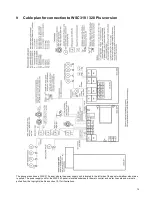
Both slave and break glass units are connected to
the master on input X5 like above example 1
–
limiting the available cable length.
Slaves and break glass units are connected on both
input X5 and X6 like above example 2.
E.g. slave panels are connected to input X5 and
break glass units are connected to input X6
–
increasing the available cable length.
Even though the connecting method of panels shown in example 2 enables a physical larger system, with longer
distances between panels and break glass units, WindowMaster recommends connecting the master slave
panels as shown in example 1. As only the master panel sends smoke commands and slave panels only
responds to commands received from the master panel, the response time in example 2 is heavily increased in
comparison with the response time in example 1.
J1
Connection for power supply
J2
Power to motor line card
J3
Connection for battery (power back-up)
J4
Connection for motor line card (WCA 3M8)
J7
2 x Ethernet connection
J8
USB host. Used to store configurations and to start an event log for e.g. trouble shooting
J9
USB device. Used for remote control and to flash the panel.
J10
Connection for fieldbus card
P1
Power supply control
R / P
Reset / programming (used for firmware updates)
LED
Shows the status of the panel
Red = alarm
Yellow = fault, flashing yellow = service timer expired, time for service
Green fast flickeing = all OK (CPU working), Green constant = CPU communication stopped (possible reset or
contact WindowMaster)
↓ ↑
Close / open all windows


