


2
1
Safety information ........................................................................................................................................................ 4
1.1
Safety ................................................................................................................................................................ 4
1.2
230V AC ............................................................................................................................................................ 4
1.3
Back-up batteries .............................................................................................................................................. 4
1.4
Application ......................................................................................................................................................... 4
1.5
Cable routing and electrical connection ............................................................................................................. 4
2
Structure of the smoke panel ...................................................................................................................................... 5
3
Variants of panels ........................................................................................................................................................ 6
3.1
Comp
actSmoke™ Plus versions ....................................................................................................................... 7
3.2
Max numbers of actuators per motor line and panel ............................................................................................. 7
4
Accessories and spare parts ...................................................................................................................................... 8
5
Technical data .............................................................................................................................................................. 9
6
Mounting ..................................................................................................................................................................... 11
7
Installation .................................................................................................................................................................. 11
7.1
Cable routing ....................................................................................................................................................11
7.2
Cables into housing ..........................................................................................................................................11
7.3
Connection of safety earth wire and 230V AC ..................................................................................................11
7.4
Installation of the break glass unit, ventilation keypad and smoke detector .....................................................11
7.5
Assembly instructions .......................................................................................................................................12
8
Cable dimensioning ................................................................................................................................................... 12
8.1
Maintaining the cable functions ........................................................................................................................12
8.2
Max. cable Length ............................................................................................................................................12
8.2.1
Formula for the calculation of the maximum actuator cable length ............................................................. 12
8.2.2
Max cable length
– ±24V standard actuators .............................................................................................. 13
8.2.3
Max cable length
– actuators with MotorLink
®
............................................................................................. 13
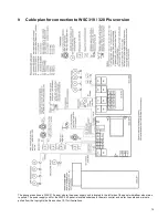
9
Cable plan for connection to WSC 310 / 320 Plus version ..................................................................................... 15
10
Description of cards and mains connection ............................................................................................................ 16
10.1
WSC 310 mains connection and power supply unit (WCA 3P1) ......................................................................16
10.2
WSC 320 mains connection and power supply unit (WCA 3P2) ......................................................................16
10.3
Connections between cards .............................................................................................................................17
10.4
Main control card WCA 3SP
– Plus Version .....................................................................................................17
10.5
Motor line card
– WCA 3M8 .............................................................................................................................28
10.6
Keypad card
– WCA 3KI ..................................................................................................................................29
10.7
Fieldbus cards ..................................................................................................................................................29
11
Cable monitoring of actuators .................................................................................................................................. 30
11.1
Usage of non-WindowMaster actuators ...........................................................................................................30
12
Back-up batteries ....................................................................................................................................................... 30
13
Touch screen .............................................................................................................................................................. 31
13.1
Icons .................................................................................................................................................................31
13.2
Rotation of the touch screen ............................................................................................................................32
14
Configuration
– main menu ....................................................................................................................................... 32
14.1
Motor lines
– motor groups – smoke zones ......................................................................................................32
14.1.1
Examples with motor lines / motor groups / smoke zones ........................................................................... 32
14.2
Motor line .........................................................................................................................................................33
14.2.1
Motor line - numbering ................................................................................................................................ 33
14.2.2
Motor line - configuration ............................................................................................................................. 33
14.2.3
Colour code - motor line .............................................................................................................................. 35
14.3
Motor group ......................................................................................................................................................35
14.3.1
Motor group - configuration ......................................................................................................................... 35
14.3.2
Colour code
– motor group .......................................................................................................................... 35
14.4
Break glass unit ................................................................................................................................................35
14.4.1
Break glass unit
– configuration .................................................................................................................. 35
14.4.2
Colour code
– break glass unit .................................................................................................................... 37
14.5
Smoke zone .....................................................................................................................................................37
14.6
Local input ........................................................................................................................................................38
14.6.1
Numbering of local inputs ............................................................................................................................ 38
14.6.2
Local input - configuration ........................................................................................................................... 39
14.6.3
Usage of wind/rain sensors - WLA 33x ...................................................................................................... 40
14.7
Local output ......................................................................................................................................................41
14.7.1
Numbering of local output ........................................................................................................................... 42
14.7.2
Local output - configuration ......................................................................................................................... 42
14.8
Weather station type ........................................................................................................................................43
14.9
Sequence control .............................................................................................................................................44
14.10
Magnetic clamp (magnetic door retainer) .........................................................................................................44
14.11
Master / Slave connection of smoke zones ......................................................................................................45
14.12
Network ............................................................................................................................................................47
14.14
Log in ...............................................................................................................................................................48
14.15
Configuration files on USB ...............................................................................................................................49
14.16
System .............................................................................................................................................................49
14.16.1
Service timer ............................................................................................................................................... 50


