120 - 23/May/97
The process of extracting the shaft position from the detected signals is done by means of a
monolithic R/D converter (see Fig. 3). The key element is the ratiometric resistive net. The
digital counter in Fig. 3 contains the shaft position information in the form of a digital word.
Specific bits of this digital word are fed to the resistive net, in order to commutate internal
resistances within the net. Analog net inputs are supplied by detected SINe and COSine
signals, fed from the resolver to the DBM module by a shielded cable. The net is made in
such a way that its output (that is, the AC error in Fig. 3) is zero if the digital word correspond
to the current shaft position, i.e. to the ratio of the SINe and COSine signals.
If the digital word does not correspond to the measured SIN/COS ratio, the AC error signal
will be generated. The amplitude of the AC error will correspond to the magnitude of the
existing difference between the SIN/COS ratio and the digital position stored in the
UP/DOWN counter. The phase of the AC errors signal is determined by the error sign. For
positive errors, the AC error will be a 10kHz sinusoid in phase with the excitation signal, and
vice versa. Due to the presence of the high frequency noise, the AC error signal has to be
filtered by an high frequency RC filter (HF FILTER block in the Fig. 3). The process of
demodulation of the error is, in effect, a form of multiplication of the AC error by the
excitation signal. As the result of this operation, an error signal is obtained, having the
average value correspondent to the R/D converter internal error. Hence, the function of the
"phase sensitive demodulator" in Fig. 3 is to express the internal angular error in the form of
a DC signal. This signal is, in turn, fed to the input of a PI error analog amplifier.. The
presence of the integral action insures that the steady state error will be zero.
The output of the PI error amplifier is fed to the UP/DOWN Voltage Controlled Oscillator. The
function of this block (see Fig. 3) is similar to the conventional VCO. The difference is that
the VCO used is able of accepting bipolar input signals. In other words, the positive input
signal fed to the VCO will produce UP counts of the digital counter, with a frequency
proportional to the magnitude of the input signal. In situations where the input to the VCO is
negative, resulting counts will be DOWN, i.e. decrementing. This way, the R/D converters
position tracking loop is closed. The digital word from the UP/DOWN counter is read by the
DSP. Position information is used for the purpose of performing the rotational transformation
of variables from the rotor d-q coordinate frame to the stator stationary a-b-c frame.
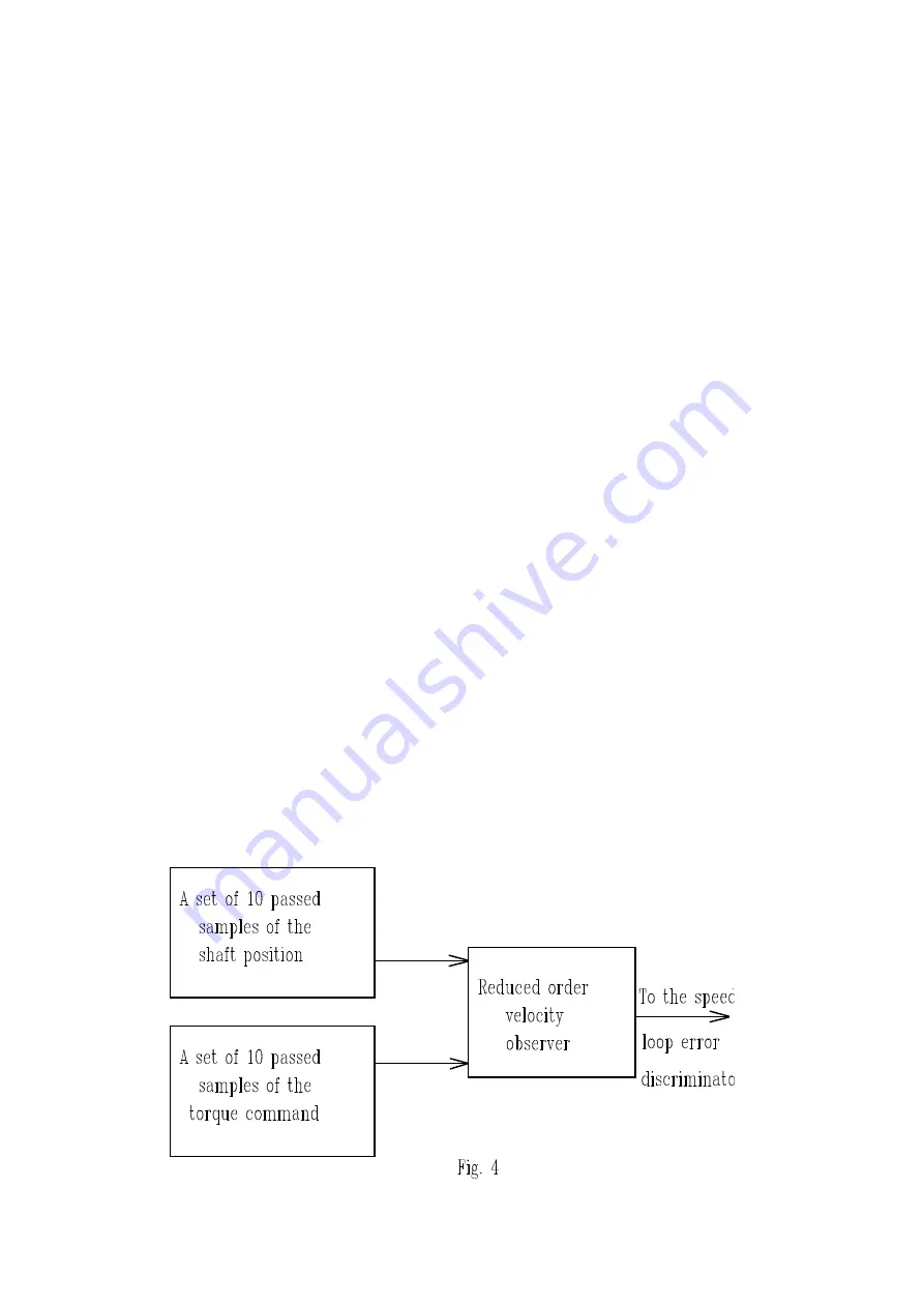
Moreover, the shaft position, taken in the form of a digital word, serves as the input to the
speed observation block, illustrated in Fig. 4:
Artisan Technology Group - Quality Instrumentation ... Guaranteed | (888) 88-SOURCE | www.artisantg.com


