


M3000
Installation Manual
86
Introduction
The M3000 Controller supports the 20 Digital Input (20DI) board, the 16 Digital Output (16DO) board, and the
16 Digital Output with Relays (16DOR) board. Although the M3000 enclosure holds up to seven boards, the
specific number of DI and DO boards supported by the different host software systems varies. Reference the
manual that came with your host system for further information on how many boards it supports.
20DI board
The 20DI board provides 20 supervised digital input (alarm) points. Supervised DIs have end-of-line resistors
on the contacts which enable the controller to detect line shorts and breaks in addition to the open and closed
contact conditions. Please note the following:
•
The maximum distance allowed between the M3000 and the alarm input device is 1,000 feet (30.48m).
•
The recommended cable wire is a two-conductor, 22-AWG shielded, stranded cable.
•
Each DI point is addressed differently depending on the host system you are using.
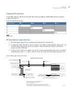
Device addressing
Picture Perfect
From one to four boards can be configured with DI points from 16 to 35. Picture Perfect addresses DIs by
board number; therefore, the DI numbers are the same for each of the possible four DI boards.
Secure Perfect
From one to four boards can be configured with DI points from 1 to 20. Addressing of DI boards follows the
format:
mmmm-b-pp
where
mmmm
represents the controller number to which this DI is associated,
b
represents
the board number, and
pp
represents the point or device number.
For example:
0001-1-01 = DI on controller 1, DI board 1, DI 1
0001-2-01 = DI on controller 1, DI board 2, DI 1
Содержание M3000
Страница 1: ...M3000 Installation Manual P N 460630001H 15JUNE11 ...
Страница 10: ...M3000 Installation Manual x ...
Страница 37: ...Chapter 3 Power Communications board 27 Host computer wiring Figure 9 Wiring host computer to first M3000 ...
Страница 39: ...Chapter 3 Power Communications board 29 Figure 11 Wiring modem to M3000 M 5 or serial printer ...
Страница 41: ...Chapter 3 Power Communications board 31 Figure 13 Wiring downstream away from the host using RS 232 ...
Страница 47: ...Chapter 4 PXNplus CPU board 37 Board layout Figure 16 PXNplus CPU board layout ...
Страница 58: ...M3000 Installation Manual 48 Board layout Figure 17 2RP reader board layout ...
Страница 65: ...Chapter 5 Reader processing boards 55 Figure 21 Wiring 2RP to Wiegand Strobed F 2F and supervised F 2F readers ...
Страница 68: ...M3000 Installation Manual 58 Figure 24 Wiring 2RP door strike external relay ...
Страница 72: ...M3000 Installation Manual 62 Board layout Figure 27 2SRP supervised reader board layout ...
Страница 78: ...M3000 Installation Manual 68 Figure 30 Wiring 2SRP to Wiegand F 2F Strobed and Supervised F 2F Readers ...
Страница 82: ...M3000 Installation Manual 72 Figure 19 Wiring 2SRP door alarm contact and exit request ...
Страница 84: ...M3000 Installation Manual 74 Figure 21 Wiring 2SRP door strike external relay ...
Страница 89: ...Chapter 5 Reader processing boards 79 Board layout Figure 24 8RP reader board layout ...
Страница 92: ...M3000 Installation Manual 82 Figure 26 Wiring 8RP to F 2F or Supervised F 2F Readers ...
Страница 94: ...M3000 Installation Manual 84 ...
Страница 97: ...Chapter 6 Optional DI and DO boards 87 Figure 31 20DI board layout ...
Страница 99: ...Chapter 6 Optional DI and DO boards 89 Figure 32 Wiring DI point ...
Страница 101: ...Chapter 6 Optional DI and DO boards 91 Figure 33 16DO board layout ...
Страница 102: ...M3000 Installation Manual 92 Figure 34 16DOR board layout ...
Страница 104: ...M3000 Installation Manual 94 Figure 36 Wiring output device to 16DOR board ...
Страница 152: ...M3000 Installation Manual 142 ...
Страница 156: ...M5 controller Installation Manual 146 Figure 76 Installing ferrite ...
Страница 160: ...M5 controller Installation Manual 150 ...
Страница 172: ...M3000 Installation Manual 162 ...


