


Chapter 5
Reader processing boards
81
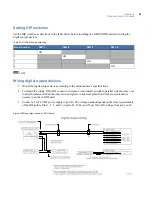
Wiring readers
To wire a reader:
1. Mount the reader. Refer to the manual that came with your reader for specific mounting instructions.
2. Run cable from the reader to the controller. Bring each reader cable through the appropriate knockout
hole in the controller cabinet. Allow some slack wire for servicing the cables and for plugging the
cable into an adjacent slot for troubleshooting.
3. Remove eight inches of insulating material from the cable. Unwrap shielding and tie all shields
together. Connect the communications cable shield to the ground nut adjacent to the cable entrance
knockout of the cabinet enclosure. For more details, see
Figure 73,
Typical installation using shielded
cable/drain wire - outside and inside the enclosure
on page 144.
4. Place the appropriate wires to the appropriate screw terminal on the 8RP reader board. Refer to the
reader wiring diagrams in this section. Pairing of cables is very important.
5. Label each cable end with Controller Address Number/ Device or Reader Number.
It is recommended that 20-AWG shielded cable be used for wiring reader DOs and DIs. Use plenum-
rated cable for applications where cable is to be run above the false (suspended) ceiling in the air
circulation space.
The following cable types are recommended:
•
Alpha Xtra Guard1® foil shield cable, non-plenum rated, and
•
Belden security and alarm cable (commercial applications shielded), plenum-rated.
CAUTION:
The
8RP board has built-in pull-up resistors. Do not install the external pull-up resistors supplied with
the UTC/GE Proximity Readers.
Table 24. Recommended pairing of reader wires - Typical reader cable)
Reader port
PIN
Signal name
Typical wire color
1/3/5/7
1
+12 VDC
Red
2
Ground
Green
3
Reader Data 1
White
4
Door DO (Reader LED)
Black
2/4/6/8
5
+12 VDC
Red
6
Ground
Green
7
Reader Data 1
White
8
Door DO (Reader LED)
Black
Содержание M3000
Страница 1: ...M3000 Installation Manual P N 460630001H 15JUNE11 ...
Страница 10: ...M3000 Installation Manual x ...
Страница 37: ...Chapter 3 Power Communications board 27 Host computer wiring Figure 9 Wiring host computer to first M3000 ...
Страница 39: ...Chapter 3 Power Communications board 29 Figure 11 Wiring modem to M3000 M 5 or serial printer ...
Страница 41: ...Chapter 3 Power Communications board 31 Figure 13 Wiring downstream away from the host using RS 232 ...
Страница 47: ...Chapter 4 PXNplus CPU board 37 Board layout Figure 16 PXNplus CPU board layout ...
Страница 58: ...M3000 Installation Manual 48 Board layout Figure 17 2RP reader board layout ...
Страница 65: ...Chapter 5 Reader processing boards 55 Figure 21 Wiring 2RP to Wiegand Strobed F 2F and supervised F 2F readers ...
Страница 68: ...M3000 Installation Manual 58 Figure 24 Wiring 2RP door strike external relay ...
Страница 72: ...M3000 Installation Manual 62 Board layout Figure 27 2SRP supervised reader board layout ...
Страница 78: ...M3000 Installation Manual 68 Figure 30 Wiring 2SRP to Wiegand F 2F Strobed and Supervised F 2F Readers ...
Страница 82: ...M3000 Installation Manual 72 Figure 19 Wiring 2SRP door alarm contact and exit request ...
Страница 84: ...M3000 Installation Manual 74 Figure 21 Wiring 2SRP door strike external relay ...
Страница 89: ...Chapter 5 Reader processing boards 79 Board layout Figure 24 8RP reader board layout ...
Страница 92: ...M3000 Installation Manual 82 Figure 26 Wiring 8RP to F 2F or Supervised F 2F Readers ...
Страница 94: ...M3000 Installation Manual 84 ...
Страница 97: ...Chapter 6 Optional DI and DO boards 87 Figure 31 20DI board layout ...
Страница 99: ...Chapter 6 Optional DI and DO boards 89 Figure 32 Wiring DI point ...
Страница 101: ...Chapter 6 Optional DI and DO boards 91 Figure 33 16DO board layout ...
Страница 102: ...M3000 Installation Manual 92 Figure 34 16DOR board layout ...
Страница 104: ...M3000 Installation Manual 94 Figure 36 Wiring output device to 16DOR board ...
Страница 152: ...M3000 Installation Manual 142 ...
Страница 156: ...M5 controller Installation Manual 146 Figure 76 Installing ferrite ...
Страница 160: ...M5 controller Installation Manual 150 ...
Страница 172: ...M3000 Installation Manual 162 ...


