M3000
Installation Manual
112
Badge Formats
Note:
This section is intended for Picture Perfect users with a working knowledge of universal badge formats. Secure
Perfect and FCWnx users should use the Other Parameters form to configure badge formats, as described on
page 117.
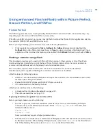
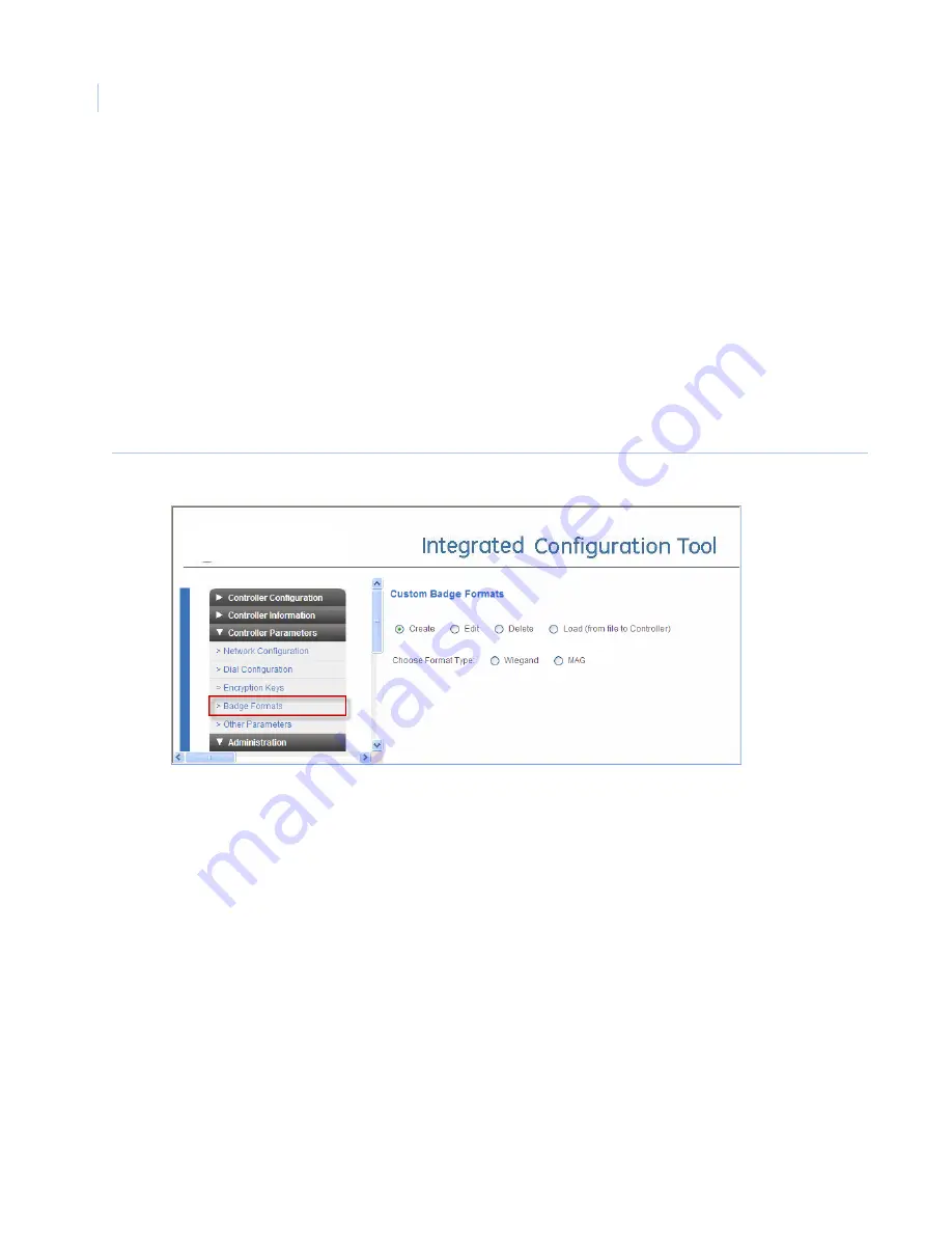
If you are running Picture Perfect, you can use the Badge Formats form (
Figure 46
) to:
•
Create a badge format, as described below.
•
Edit a badge format (page 116)
•
Delete a badge format (page 116)
•
Load a badge format (page 116)
Note:
Due to the complexity involved in creating a Wiegand badge format, we recommend that you contact Technical
Support for assistance before beginning those steps.
Figure 46.
Controller Parameters/Badge Formats - Create form
Create a badge format
This section describes how to create a new badge format using either Wiegand or MAG (i.e., magnetic) format.
1. If you have not already done so, log on to the Integrated Configuration Tool. See
To start the
Integrated Configuration Tool:
on page 102.
2. From the
Controller Parameters
menu, select
Badge Formats
.
3. Select
Create
.
4. In the
Choose Format Type
field, select the format type:
•
If you select
Wiegand
as the format type
, you will need to specify how many total bits are in the
format, how many characters are in the actual badge data used to represent facility bits, and how
many characters will be used to encode the badge number. Continue to step 5.
Note:
Before creating a Wiegand badge format, contact Technical Support for assistance.
•
If you select
MAG
as the format type
, skip ahead to
MAG badge format options
on page 114.
Wiegand badge format options
5. In the
Format Name
field, enter a unique ID for the type of badge format you are creating.
Содержание M3000
Страница 1: ...M3000 Installation Manual P N 460630001H 15JUNE11 ...
Страница 10: ...M3000 Installation Manual x ...
Страница 37: ...Chapter 3 Power Communications board 27 Host computer wiring Figure 9 Wiring host computer to first M3000 ...
Страница 39: ...Chapter 3 Power Communications board 29 Figure 11 Wiring modem to M3000 M 5 or serial printer ...
Страница 41: ...Chapter 3 Power Communications board 31 Figure 13 Wiring downstream away from the host using RS 232 ...
Страница 47: ...Chapter 4 PXNplus CPU board 37 Board layout Figure 16 PXNplus CPU board layout ...
Страница 58: ...M3000 Installation Manual 48 Board layout Figure 17 2RP reader board layout ...
Страница 65: ...Chapter 5 Reader processing boards 55 Figure 21 Wiring 2RP to Wiegand Strobed F 2F and supervised F 2F readers ...
Страница 68: ...M3000 Installation Manual 58 Figure 24 Wiring 2RP door strike external relay ...
Страница 72: ...M3000 Installation Manual 62 Board layout Figure 27 2SRP supervised reader board layout ...
Страница 78: ...M3000 Installation Manual 68 Figure 30 Wiring 2SRP to Wiegand F 2F Strobed and Supervised F 2F Readers ...
Страница 82: ...M3000 Installation Manual 72 Figure 19 Wiring 2SRP door alarm contact and exit request ...
Страница 84: ...M3000 Installation Manual 74 Figure 21 Wiring 2SRP door strike external relay ...
Страница 89: ...Chapter 5 Reader processing boards 79 Board layout Figure 24 8RP reader board layout ...
Страница 92: ...M3000 Installation Manual 82 Figure 26 Wiring 8RP to F 2F or Supervised F 2F Readers ...
Страница 94: ...M3000 Installation Manual 84 ...
Страница 97: ...Chapter 6 Optional DI and DO boards 87 Figure 31 20DI board layout ...
Страница 99: ...Chapter 6 Optional DI and DO boards 89 Figure 32 Wiring DI point ...
Страница 101: ...Chapter 6 Optional DI and DO boards 91 Figure 33 16DO board layout ...
Страница 102: ...M3000 Installation Manual 92 Figure 34 16DOR board layout ...
Страница 104: ...M3000 Installation Manual 94 Figure 36 Wiring output device to 16DOR board ...
Страница 152: ...M3000 Installation Manual 142 ...
Страница 156: ...M5 controller Installation Manual 146 Figure 76 Installing ferrite ...
Страница 160: ...M5 controller Installation Manual 150 ...
Страница 172: ...M3000 Installation Manual 162 ...

