


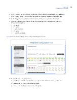

Chapter 8
Controller firmware tools
99
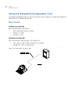
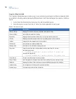
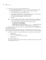
Figure 38.Connecting through network hub
Before you continue
Answer these questions before continuing:
•
Is there a firewall on the computer you are using to access the Integrated Configuration Tool?
If so, you will need to disable it in order to use the Integrated Configuration Tool.
•
Is your network using a proxy?
If so, you will need to disable the proxy or bypass it.
Complete the
Configuration checklist for Integrated Configuration Tool
on page 123 for each controller that
you will be setting up.
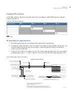
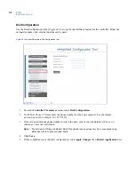
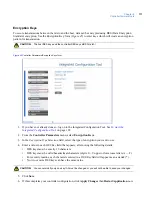
Initial configuration
By default, the controller’s IP address is
192.168.6.6
. To have your computer communicate with the
controller, you must set your computer IP address to
192.168.6.5
, or similar valid IP address
(
192.168.6.
x
where
x
is any number between 1 and 254 except 6). The steps required to change the IP
address depend on whether you are running Windows 2000, Windows XP, or Windows 7, as described next.
Initial configuration: Windows 2000
1. Click
Start
,
Settings
, then
Network and Dial-up Connections
.
2. Right-click on
Local Area Connection.
If the first option in the drop-down list box is:
•
Disable
, then the connection is enabled. Continue to
step 3
.
•
Enable
, then select it to enable the connection and return to
step 1
.
3. Select
Properties
from the drop-down list box.
4. In the
Components checked are used in this connection
section, select
Internet Protocol TCP/IP
.
5. Click
Properties
.
Содержание M3000
Страница 1: ...M3000 Installation Manual P N 460630001H 15JUNE11 ...
Страница 10: ...M3000 Installation Manual x ...
Страница 37: ...Chapter 3 Power Communications board 27 Host computer wiring Figure 9 Wiring host computer to first M3000 ...
Страница 39: ...Chapter 3 Power Communications board 29 Figure 11 Wiring modem to M3000 M 5 or serial printer ...
Страница 41: ...Chapter 3 Power Communications board 31 Figure 13 Wiring downstream away from the host using RS 232 ...
Страница 47: ...Chapter 4 PXNplus CPU board 37 Board layout Figure 16 PXNplus CPU board layout ...
Страница 58: ...M3000 Installation Manual 48 Board layout Figure 17 2RP reader board layout ...
Страница 65: ...Chapter 5 Reader processing boards 55 Figure 21 Wiring 2RP to Wiegand Strobed F 2F and supervised F 2F readers ...
Страница 68: ...M3000 Installation Manual 58 Figure 24 Wiring 2RP door strike external relay ...
Страница 72: ...M3000 Installation Manual 62 Board layout Figure 27 2SRP supervised reader board layout ...
Страница 78: ...M3000 Installation Manual 68 Figure 30 Wiring 2SRP to Wiegand F 2F Strobed and Supervised F 2F Readers ...
Страница 82: ...M3000 Installation Manual 72 Figure 19 Wiring 2SRP door alarm contact and exit request ...
Страница 84: ...M3000 Installation Manual 74 Figure 21 Wiring 2SRP door strike external relay ...
Страница 89: ...Chapter 5 Reader processing boards 79 Board layout Figure 24 8RP reader board layout ...
Страница 92: ...M3000 Installation Manual 82 Figure 26 Wiring 8RP to F 2F or Supervised F 2F Readers ...
Страница 94: ...M3000 Installation Manual 84 ...
Страница 97: ...Chapter 6 Optional DI and DO boards 87 Figure 31 20DI board layout ...
Страница 99: ...Chapter 6 Optional DI and DO boards 89 Figure 32 Wiring DI point ...
Страница 101: ...Chapter 6 Optional DI and DO boards 91 Figure 33 16DO board layout ...
Страница 102: ...M3000 Installation Manual 92 Figure 34 16DOR board layout ...
Страница 104: ...M3000 Installation Manual 94 Figure 36 Wiring output device to 16DOR board ...
Страница 152: ...M3000 Installation Manual 142 ...
Страница 156: ...M5 controller Installation Manual 146 Figure 76 Installing ferrite ...
Страница 160: ...M5 controller Installation Manual 150 ...
Страница 172: ...M3000 Installation Manual 162 ...


