


Chapter 8
Controller firmware tools
103
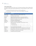
Saving configuration changes
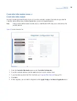
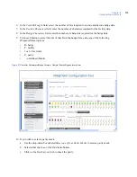
Before using the Integrated Configuration Tool, note the following details about saving your changes:
•
If you change any options on a page, you must click the
Save
button (see
Figure 39
) to save your
changes before switching to another page. This action saves your latest changes to a temporary file.
•
Select
Apply Changes
from the Administration menu after you have made all necessary changes in
the Integrated Configuration Tool. You will be prompted to restart either the application or the
controller and your changes will be saved to the controller’s
config
file.
•
If you click
Save
on each page, you do not need to apply changes or restart the application until you
are finished making all necessary changes.
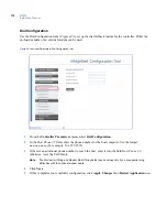
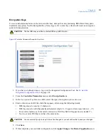
Figure 39.
Saving changes in the Integrated Configuration Tool
Table 33
summarizes how the
Save
button and the
Apply Changes
menu option operate.
Table 33. Buttons available and when to use them
Button
Usage
Result
Save
After making changes on any page
Saves the changes to the shadow config.txt
file located in the /var/tmp directory.
Apply Changes
After all the changes are complete
Saves the changes from the shadow
config.txt file to the real config.txt file
located in the /opt/config directory.
Restart Application
After clicking Apply Changes
The application picks up the latest changes
from the config.txt file and starts again.
Restart Controller
After clicking Apply Changes
The operating system picks up the latest
changes and starts again.
Содержание M3000
Страница 1: ...M3000 Installation Manual P N 460630001H 15JUNE11 ...
Страница 10: ...M3000 Installation Manual x ...
Страница 37: ...Chapter 3 Power Communications board 27 Host computer wiring Figure 9 Wiring host computer to first M3000 ...
Страница 39: ...Chapter 3 Power Communications board 29 Figure 11 Wiring modem to M3000 M 5 or serial printer ...
Страница 41: ...Chapter 3 Power Communications board 31 Figure 13 Wiring downstream away from the host using RS 232 ...
Страница 47: ...Chapter 4 PXNplus CPU board 37 Board layout Figure 16 PXNplus CPU board layout ...
Страница 58: ...M3000 Installation Manual 48 Board layout Figure 17 2RP reader board layout ...
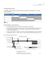
Страница 65: ...Chapter 5 Reader processing boards 55 Figure 21 Wiring 2RP to Wiegand Strobed F 2F and supervised F 2F readers ...
Страница 68: ...M3000 Installation Manual 58 Figure 24 Wiring 2RP door strike external relay ...
Страница 72: ...M3000 Installation Manual 62 Board layout Figure 27 2SRP supervised reader board layout ...
Страница 78: ...M3000 Installation Manual 68 Figure 30 Wiring 2SRP to Wiegand F 2F Strobed and Supervised F 2F Readers ...
Страница 82: ...M3000 Installation Manual 72 Figure 19 Wiring 2SRP door alarm contact and exit request ...
Страница 84: ...M3000 Installation Manual 74 Figure 21 Wiring 2SRP door strike external relay ...
Страница 89: ...Chapter 5 Reader processing boards 79 Board layout Figure 24 8RP reader board layout ...
Страница 92: ...M3000 Installation Manual 82 Figure 26 Wiring 8RP to F 2F or Supervised F 2F Readers ...
Страница 94: ...M3000 Installation Manual 84 ...
Страница 97: ...Chapter 6 Optional DI and DO boards 87 Figure 31 20DI board layout ...
Страница 99: ...Chapter 6 Optional DI and DO boards 89 Figure 32 Wiring DI point ...
Страница 101: ...Chapter 6 Optional DI and DO boards 91 Figure 33 16DO board layout ...
Страница 102: ...M3000 Installation Manual 92 Figure 34 16DOR board layout ...
Страница 104: ...M3000 Installation Manual 94 Figure 36 Wiring output device to 16DOR board ...
Страница 152: ...M3000 Installation Manual 142 ...
Страница 156: ...M5 controller Installation Manual 146 Figure 76 Installing ferrite ...
Страница 160: ...M5 controller Installation Manual 150 ...
Страница 172: ...M3000 Installation Manual 162 ...


