


Chapter 5
Reader processing boards
71
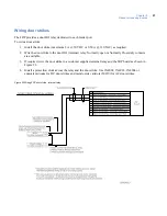
Wiring DIs
Each reader port has two supervised digital inputs which are used for door status devices (door contacts and
exit request input). Since these digital inputs are supervised, they require end-of-line resistors.
To wire a DI:
1. Follow the installation specifications for the device. Mount the device according to the manufacturer’s
specifications. The alarm device (door contact) should have a dry contact which can have a Normally
Open or Normally Closed type switch. A Normally Closed contact is in its normal or resting position
when it is closed. For example, the contact is closed when the door is closed. The opposite is true for a
Normally Open contact. In this case, the contact is open when the door is closed.
2. Select the appropriate digital input for each alarm input device.
3. Ground the shields of the cable at the M3000 enclosure grounding studs. Insulate the shield (with tape
or shrink tubing) at the DI device end to avoid electrical noise.
4. Install two end-of-line resistors. Install each resistor as close to the door status contact as possible.
5. We recommend the standard 1,000 (1K) ohm, 1/4 watt, 5% tolerance, high-quality end-of-line
resistors. This board also supports 6.8K and 18K end-of-line resistors. See
Figure 19
on page 72 for
the location of the resistors. See
Table 26,
Supervised DI end-of-line resistors
on page 63 for the
appropriate switch settings.
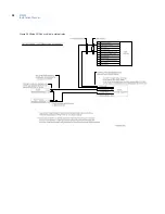
6. Wire the supervised door DI between pin 8 (Door DI) and pin 9 (Door DI Return). Wire the supervised
exit DI between pin 5 (Exit DI) and pin 10 (Exit DI Return). The contact can be Normally Open or
Normally Closed.
7. Insulate resistors with tape or heat shrink tubing.
8. Document how you wired the alarm input devices. Future expansion of the system and its maintenance
depend upon accurate documentation.
CAUTION:
The supervision capability will be impaired if the resistors are NOT wired immediately adjacent to the
door status contact.
Содержание M3000
Страница 1: ...M3000 Installation Manual P N 460630001H 15JUNE11 ...
Страница 10: ...M3000 Installation Manual x ...
Страница 37: ...Chapter 3 Power Communications board 27 Host computer wiring Figure 9 Wiring host computer to first M3000 ...
Страница 39: ...Chapter 3 Power Communications board 29 Figure 11 Wiring modem to M3000 M 5 or serial printer ...
Страница 41: ...Chapter 3 Power Communications board 31 Figure 13 Wiring downstream away from the host using RS 232 ...
Страница 47: ...Chapter 4 PXNplus CPU board 37 Board layout Figure 16 PXNplus CPU board layout ...
Страница 58: ...M3000 Installation Manual 48 Board layout Figure 17 2RP reader board layout ...
Страница 65: ...Chapter 5 Reader processing boards 55 Figure 21 Wiring 2RP to Wiegand Strobed F 2F and supervised F 2F readers ...
Страница 68: ...M3000 Installation Manual 58 Figure 24 Wiring 2RP door strike external relay ...
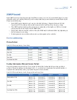
Страница 72: ...M3000 Installation Manual 62 Board layout Figure 27 2SRP supervised reader board layout ...
Страница 78: ...M3000 Installation Manual 68 Figure 30 Wiring 2SRP to Wiegand F 2F Strobed and Supervised F 2F Readers ...
Страница 82: ...M3000 Installation Manual 72 Figure 19 Wiring 2SRP door alarm contact and exit request ...
Страница 84: ...M3000 Installation Manual 74 Figure 21 Wiring 2SRP door strike external relay ...
Страница 89: ...Chapter 5 Reader processing boards 79 Board layout Figure 24 8RP reader board layout ...
Страница 92: ...M3000 Installation Manual 82 Figure 26 Wiring 8RP to F 2F or Supervised F 2F Readers ...
Страница 94: ...M3000 Installation Manual 84 ...
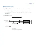
Страница 97: ...Chapter 6 Optional DI and DO boards 87 Figure 31 20DI board layout ...
Страница 99: ...Chapter 6 Optional DI and DO boards 89 Figure 32 Wiring DI point ...
Страница 101: ...Chapter 6 Optional DI and DO boards 91 Figure 33 16DO board layout ...
Страница 102: ...M3000 Installation Manual 92 Figure 34 16DOR board layout ...
Страница 104: ...M3000 Installation Manual 94 Figure 36 Wiring output device to 16DOR board ...
Страница 152: ...M3000 Installation Manual 142 ...
Страница 156: ...M5 controller Installation Manual 146 Figure 76 Installing ferrite ...
Страница 160: ...M5 controller Installation Manual 150 ...
Страница 172: ...M3000 Installation Manual 162 ...


