


Chapter 8
Controller firmware tools
131
Secure Perfect
The following procedures were developed using Secure Perfect 6.1.1. Some forms may vary depending upon
the version of Secure Perfect you are using.
This feature is not available for controllers not running the Secure Perfect application code.
Flash Micro
is an
enhanced flash method which does not require the controller to be in maintenance mode.
The
Operations
menu,
Micro Utility
Form of the Secure Perfect application allows you to monitor
communications and manage each controller in the system. You can identify the controllers using the
Search
Criteria and Micro Selection
. (Refer to the
Secure Perfect User Manual
or Online Help for additional
information.) The procedure to flash has been integrated so that the controller stays online and continues to
process badge and alarm activity while in the process of being flashed.
For more information about:
•
Flashing controllers, go to
Flashing controllers
on page 131.
•
Viewing/editing parameter information, go to
View/edit parameter information
on page 133.
Flashing controllers
To flash controllers that already have SP3.x firmware:
1. Verify that the Secure Perfect services are running (refer to the appropriate section of the
Installation
Manual
for the system you purchased).
2. Log on to the Secure Perfect program. The login ID and password must belong to a member of the
spadmin local user group on the Secure Perfect Server computer and the user group on any Secure
Perfect client computer.)
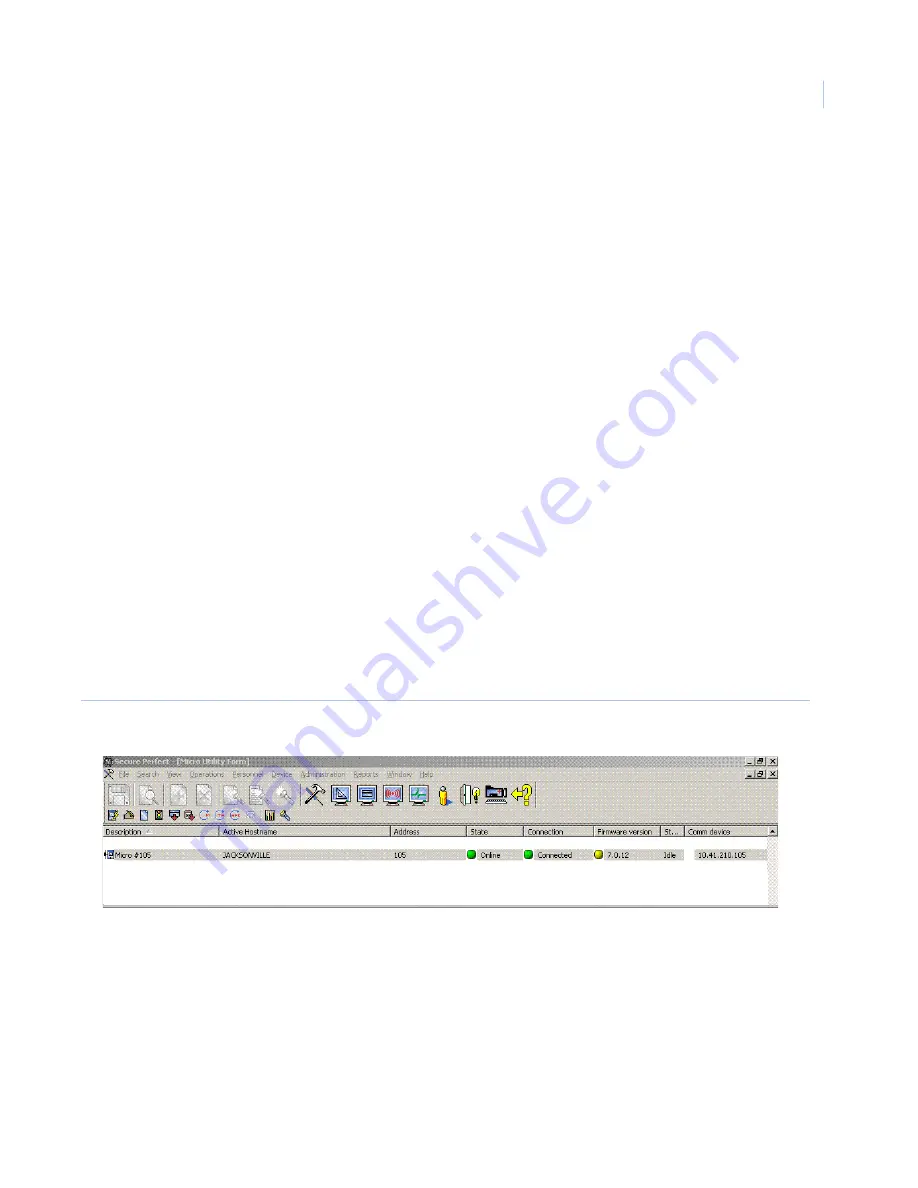
3. Verify that the controller is online. In the Secure Perfect program, select the
Operations
menu,
Micro
Utility Form
. Check the
State
column.
Figure 55.Secure Perfect Micro Utility Form
4. Select the controller or multiple controllers that you want to flash. If flashing a line of controllers, we
recommend starting with the end-of-line controller, and work toward the head-of-line controller. This
requires a working knowledge of your Secure Perfect system.
Note:
When flashing a line of controllers with a PXNplus controller as the head-of-line controller, only two
downstream controllers can be selected at a time.
Result:
The firmware version column on the
Micro Utility Form
displays the current firmware on the
controller.
•
If the LED is green, the firmware on the controller matches the latest firmware on the Server
computer.
Содержание M3000
Страница 1: ...M3000 Installation Manual P N 460630001H 15JUNE11 ...
Страница 10: ...M3000 Installation Manual x ...
Страница 37: ...Chapter 3 Power Communications board 27 Host computer wiring Figure 9 Wiring host computer to first M3000 ...
Страница 39: ...Chapter 3 Power Communications board 29 Figure 11 Wiring modem to M3000 M 5 or serial printer ...
Страница 41: ...Chapter 3 Power Communications board 31 Figure 13 Wiring downstream away from the host using RS 232 ...
Страница 47: ...Chapter 4 PXNplus CPU board 37 Board layout Figure 16 PXNplus CPU board layout ...
Страница 58: ...M3000 Installation Manual 48 Board layout Figure 17 2RP reader board layout ...
Страница 65: ...Chapter 5 Reader processing boards 55 Figure 21 Wiring 2RP to Wiegand Strobed F 2F and supervised F 2F readers ...
Страница 68: ...M3000 Installation Manual 58 Figure 24 Wiring 2RP door strike external relay ...
Страница 72: ...M3000 Installation Manual 62 Board layout Figure 27 2SRP supervised reader board layout ...
Страница 78: ...M3000 Installation Manual 68 Figure 30 Wiring 2SRP to Wiegand F 2F Strobed and Supervised F 2F Readers ...
Страница 82: ...M3000 Installation Manual 72 Figure 19 Wiring 2SRP door alarm contact and exit request ...
Страница 84: ...M3000 Installation Manual 74 Figure 21 Wiring 2SRP door strike external relay ...
Страница 89: ...Chapter 5 Reader processing boards 79 Board layout Figure 24 8RP reader board layout ...
Страница 92: ...M3000 Installation Manual 82 Figure 26 Wiring 8RP to F 2F or Supervised F 2F Readers ...
Страница 94: ...M3000 Installation Manual 84 ...
Страница 97: ...Chapter 6 Optional DI and DO boards 87 Figure 31 20DI board layout ...
Страница 99: ...Chapter 6 Optional DI and DO boards 89 Figure 32 Wiring DI point ...
Страница 101: ...Chapter 6 Optional DI and DO boards 91 Figure 33 16DO board layout ...
Страница 102: ...M3000 Installation Manual 92 Figure 34 16DOR board layout ...
Страница 104: ...M3000 Installation Manual 94 Figure 36 Wiring output device to 16DOR board ...
Страница 152: ...M3000 Installation Manual 142 ...
Страница 156: ...M5 controller Installation Manual 146 Figure 76 Installing ferrite ...
Страница 160: ...M5 controller Installation Manual 150 ...
Страница 172: ...M3000 Installation Manual 162 ...


