


M3000
Installation Manual
38
Pins and jumpers
General purpose pins
Modem control jumper - J10
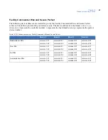
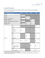
Table 11. General purpose pins
Pins
Shorting these pins...
JP2
Boot Mode
This function is for manufacturing and catastrophic failure recovery only!
Returns the
board to boot maintenance mode which allows for burning in of a new boot image.
JP3
Shutdown Request
Stops the application and puts the board into maintenance mode which allows the board to
be removed. Since the PXNplus board runs an operating system just like a computer, it
must be shut down correctly. Shorting JP3 shuts down the operating system/application of
the board. JP3 is like using the “Shut down” feature on your computer.
To properly restart the board use both JP3 and JP6.
First, short JP3 to stop the
application, then short JP6 to restart (reset) the board.
JP4
Restore Defaults
Returns the configuration to the factory defaults:
•
Primary Connection Type:
Ethernet
•
IP Address:
192.168.6.6
•
Mask:
255.255.255.0
•
Gateway:
192.168.6.1
Short JP4 for a
minimum
of five seconds.
JP6
Hardware Reset
Reboots the CPU board without properly shutting down the application. The PXNplus board
runs an operating system just like a computer. Shorting JP6 is like pressing the Off button
on your computer without using the “Shut down” feature. The controller shuts down but not
in a clean way.
To properly restart the board use both JP3 and JP6.
First, short JP3 to stop the
application, then short JP6 to restart (reset) the board.
CAUTION:
Earlier lines of controllers sometimes required the “wrap plug” to force the CPU into maintenance
mode. DO NOT use the wrap plug on the PXNplus CPU board. To properly set the controller into
maintenance mode, short JP3 (Shutdown Request) for about 5 seconds until DS7 turns on. DS2 and
DS3 will then alternate ON and OFF.
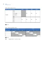
Table 12. Modem control jumper
J10
Pins
Function
1 and 2
1
1.
This is the default setting. If the jumper is missing, the default setting is used.
Upstream direct using J3 on the Power/Communications board
2 and 3
On-board modem on the CPU board
Содержание M3000
Страница 1: ...M3000 Installation Manual P N 460630001H 15JUNE11 ...
Страница 10: ...M3000 Installation Manual x ...
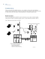
Страница 37: ...Chapter 3 Power Communications board 27 Host computer wiring Figure 9 Wiring host computer to first M3000 ...
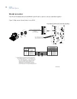
Страница 39: ...Chapter 3 Power Communications board 29 Figure 11 Wiring modem to M3000 M 5 or serial printer ...
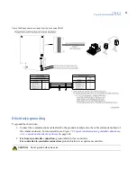
Страница 41: ...Chapter 3 Power Communications board 31 Figure 13 Wiring downstream away from the host using RS 232 ...
Страница 47: ...Chapter 4 PXNplus CPU board 37 Board layout Figure 16 PXNplus CPU board layout ...
Страница 58: ...M3000 Installation Manual 48 Board layout Figure 17 2RP reader board layout ...
Страница 65: ...Chapter 5 Reader processing boards 55 Figure 21 Wiring 2RP to Wiegand Strobed F 2F and supervised F 2F readers ...
Страница 68: ...M3000 Installation Manual 58 Figure 24 Wiring 2RP door strike external relay ...
Страница 72: ...M3000 Installation Manual 62 Board layout Figure 27 2SRP supervised reader board layout ...
Страница 78: ...M3000 Installation Manual 68 Figure 30 Wiring 2SRP to Wiegand F 2F Strobed and Supervised F 2F Readers ...
Страница 82: ...M3000 Installation Manual 72 Figure 19 Wiring 2SRP door alarm contact and exit request ...
Страница 84: ...M3000 Installation Manual 74 Figure 21 Wiring 2SRP door strike external relay ...
Страница 89: ...Chapter 5 Reader processing boards 79 Board layout Figure 24 8RP reader board layout ...
Страница 92: ...M3000 Installation Manual 82 Figure 26 Wiring 8RP to F 2F or Supervised F 2F Readers ...
Страница 94: ...M3000 Installation Manual 84 ...
Страница 97: ...Chapter 6 Optional DI and DO boards 87 Figure 31 20DI board layout ...
Страница 99: ...Chapter 6 Optional DI and DO boards 89 Figure 32 Wiring DI point ...
Страница 101: ...Chapter 6 Optional DI and DO boards 91 Figure 33 16DO board layout ...
Страница 102: ...M3000 Installation Manual 92 Figure 34 16DOR board layout ...
Страница 104: ...M3000 Installation Manual 94 Figure 36 Wiring output device to 16DOR board ...
Страница 152: ...M3000 Installation Manual 142 ...
Страница 156: ...M5 controller Installation Manual 146 Figure 76 Installing ferrite ...
Страница 160: ...M5 controller Installation Manual 150 ...
Страница 172: ...M3000 Installation Manual 162 ...


