Chapter 4
PXNplus CPU board
41
Table 14
shows the LED state transitions. See
Chapter 10
Troubleshooting, maintenance & support
for error
conditions. See
Figure 16,
PXNplus CPU board layout
on page 37 for the location of the LEDs.
Modem LED indicators on the PXNplus CPU board
If your PXNplus CPU board includes an optional modem (P/N 521257001),
Table 15
shows the LED state
transitions. (See
Figure 16,
PXNplus CPU board layout
on page 37 for the location of the LED indicators.)
Table 14. PXNplus CPU board LED normal state transitions
DS1
DS2
DS3
DS4
DS5
DS6
DS7
DS8
During power up
ON
ON
ON
ON
ON
ON
ON
ON
Boot maintenance mode
ON
OS (Operating system)
maintenance mode
Alternates
ON with
DS3
Alternates
ON with
DS2
ON
Normal operation mode
Controller offline
ON
Address received
Flashes
once
Badge read OK
Flashes
once
Waiting for database
Flashes
1
1.
For Picture Perfect systems: DS4 blinks once per second.
For Secure Perfect systems: DS4 blinks twice followed by a one-second delay before repeating.
= OFF
Restore defaults
requested
ON
ON
Shutdown requested
ON
ON
eFlash image save
Alternates
ON with
DS8
Alternates
ON with
DS7
Persistence
ON
Flash Write
Flashing
Watchdog failure mode
ON
ON
Table 15. Modem LEDs on the PXNplus CPU board
LED number
Name
Description
DS13
DCD - Data Carrier Detect
Modems are connected.
DS14
CTS - Clear To Send
Modem is ready to send data.
Содержание M3000
Страница 1: ...M3000 Installation Manual P N 460630001H 15JUNE11 ...
Страница 10: ...M3000 Installation Manual x ...
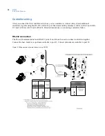
Страница 37: ...Chapter 3 Power Communications board 27 Host computer wiring Figure 9 Wiring host computer to first M3000 ...
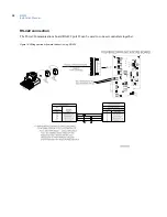
Страница 39: ...Chapter 3 Power Communications board 29 Figure 11 Wiring modem to M3000 M 5 or serial printer ...
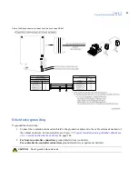
Страница 41: ...Chapter 3 Power Communications board 31 Figure 13 Wiring downstream away from the host using RS 232 ...
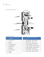
Страница 47: ...Chapter 4 PXNplus CPU board 37 Board layout Figure 16 PXNplus CPU board layout ...
Страница 58: ...M3000 Installation Manual 48 Board layout Figure 17 2RP reader board layout ...
Страница 65: ...Chapter 5 Reader processing boards 55 Figure 21 Wiring 2RP to Wiegand Strobed F 2F and supervised F 2F readers ...
Страница 68: ...M3000 Installation Manual 58 Figure 24 Wiring 2RP door strike external relay ...
Страница 72: ...M3000 Installation Manual 62 Board layout Figure 27 2SRP supervised reader board layout ...
Страница 78: ...M3000 Installation Manual 68 Figure 30 Wiring 2SRP to Wiegand F 2F Strobed and Supervised F 2F Readers ...
Страница 82: ...M3000 Installation Manual 72 Figure 19 Wiring 2SRP door alarm contact and exit request ...
Страница 84: ...M3000 Installation Manual 74 Figure 21 Wiring 2SRP door strike external relay ...
Страница 89: ...Chapter 5 Reader processing boards 79 Board layout Figure 24 8RP reader board layout ...
Страница 92: ...M3000 Installation Manual 82 Figure 26 Wiring 8RP to F 2F or Supervised F 2F Readers ...
Страница 94: ...M3000 Installation Manual 84 ...
Страница 97: ...Chapter 6 Optional DI and DO boards 87 Figure 31 20DI board layout ...
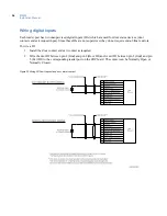
Страница 99: ...Chapter 6 Optional DI and DO boards 89 Figure 32 Wiring DI point ...
Страница 101: ...Chapter 6 Optional DI and DO boards 91 Figure 33 16DO board layout ...
Страница 102: ...M3000 Installation Manual 92 Figure 34 16DOR board layout ...
Страница 104: ...M3000 Installation Manual 94 Figure 36 Wiring output device to 16DOR board ...
Страница 152: ...M3000 Installation Manual 142 ...
Страница 156: ...M5 controller Installation Manual 146 Figure 76 Installing ferrite ...
Страница 160: ...M5 controller Installation Manual 150 ...
Страница 172: ...M3000 Installation Manual 162 ...


