M3000
Installation Manual
118
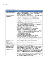
Table 35. Parameters/Other Parameters options
Parameter
Description
Change Username/Password
Set the username and/or the password used to log on to the Integrated Configuration
Tool. By default, these values are set to “install, install”. For increased security, we
recommend that you change the default values.
Enable/Disable Integrated
Configuration Tool
Control access to the Integrated Configuration Tool by selecting one of two options:
• Temporary allows access to the Tool until the controller resets.
• Permanent allows access until you manually disable the Tool again.
Note:
Before you begin, you MUST have physical access to the controller.
To enable the Integrated Configuration Tool
temporarily
:
1. Verify that the controller has completed the power-up boot cycle by checking
that DS7 is no longer in the constant ON state.
2. Verify that DS6 turns ON. Allow up to five seconds for DS6 to turn ON. Once
DS6 is ON, remove the jumper and DS6 turns OFF.
3. The Integrated Configuration Tool is now enabled until the controller reboots.
To enable the Integrated Configuration Tool
permanently
:
1. Complete the steps to enable the tool temporarily, as listed above.
2. Log on to the Integrated Configuration Tool.
3. From the
Controller Parameters
menu, select
Other Parameters
.
4. Select
Enable Integrated Configuration Tool
, then click
OK
.
5. To make this selection permanent, click
Save
,
Apply Changes,
then
Restart
Controller
. The controller performs a system reboot automatically and the
Integrated Configuration Tool is permanently enabled.
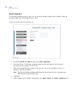
To disable the Integrated Configuration Tool:
1. Log on to the Integrated Configuration Tool.
2. From the Controller Parameters menu, select Other Parameters.
3. Select
Disable Integrated Configuration Tool
, then click
OK
.
4. To make this selection permanent, click
Save
,
Apply Changes,
then
Restart
Controller
. The controller performs a system reboot automatically and the
Integrated Configuration Tool is permanently disabled.
WIU default badge format,
4001/4002
Set the default bit format used for a Weigand Interface Unit (WIU).
F/2F Reader DOOR
CONTACT/REX input source
Determine the edge of the door contact that will be read.
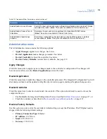
End-of-Line resistor values
Set the values used to terminate protective loops or zones.
Set Badge History vs Alarm
History Memory Allocation
Determine the percentage of memory allocated for badge and alarm history, from 10
to 90 percent. (
Note:
This option is available for Picture Perfect only. For Secure
Perfect/FCWnx, this value is fixed at 50% and is not user configurable.)
Set Resistor Tolerances
Set the range in which voltage can change before a 4-state DI state is detected. After
you check the Set Resistor Tolerances check box, enter a
Res Tol # 1
value. (
Note:
The
Res Tol # 2
and
Res Tol # 3
values are reserved so the fields are read-only.)
Enable/Disable Idle Poll Timer
Control network activity between the controller and the host. The poll timer
guarantees that the connection between the controller and the host is not shut down
by the network administrator, firewall, or other device due to network inactivity.
(
Note:
This option is available for Picture Perfect only.)
Содержание M3000
Страница 1: ...M3000 Installation Manual P N 460630001H 15JUNE11 ...
Страница 10: ...M3000 Installation Manual x ...
Страница 37: ...Chapter 3 Power Communications board 27 Host computer wiring Figure 9 Wiring host computer to first M3000 ...
Страница 39: ...Chapter 3 Power Communications board 29 Figure 11 Wiring modem to M3000 M 5 or serial printer ...
Страница 41: ...Chapter 3 Power Communications board 31 Figure 13 Wiring downstream away from the host using RS 232 ...
Страница 47: ...Chapter 4 PXNplus CPU board 37 Board layout Figure 16 PXNplus CPU board layout ...
Страница 58: ...M3000 Installation Manual 48 Board layout Figure 17 2RP reader board layout ...
Страница 65: ...Chapter 5 Reader processing boards 55 Figure 21 Wiring 2RP to Wiegand Strobed F 2F and supervised F 2F readers ...
Страница 68: ...M3000 Installation Manual 58 Figure 24 Wiring 2RP door strike external relay ...
Страница 72: ...M3000 Installation Manual 62 Board layout Figure 27 2SRP supervised reader board layout ...
Страница 78: ...M3000 Installation Manual 68 Figure 30 Wiring 2SRP to Wiegand F 2F Strobed and Supervised F 2F Readers ...
Страница 82: ...M3000 Installation Manual 72 Figure 19 Wiring 2SRP door alarm contact and exit request ...
Страница 84: ...M3000 Installation Manual 74 Figure 21 Wiring 2SRP door strike external relay ...
Страница 89: ...Chapter 5 Reader processing boards 79 Board layout Figure 24 8RP reader board layout ...
Страница 92: ...M3000 Installation Manual 82 Figure 26 Wiring 8RP to F 2F or Supervised F 2F Readers ...
Страница 94: ...M3000 Installation Manual 84 ...
Страница 97: ...Chapter 6 Optional DI and DO boards 87 Figure 31 20DI board layout ...
Страница 99: ...Chapter 6 Optional DI and DO boards 89 Figure 32 Wiring DI point ...
Страница 101: ...Chapter 6 Optional DI and DO boards 91 Figure 33 16DO board layout ...
Страница 102: ...M3000 Installation Manual 92 Figure 34 16DOR board layout ...
Страница 104: ...M3000 Installation Manual 94 Figure 36 Wiring output device to 16DOR board ...
Страница 152: ...M3000 Installation Manual 142 ...
Страница 156: ...M5 controller Installation Manual 146 Figure 76 Installing ferrite ...
Страница 160: ...M5 controller Installation Manual 150 ...
Страница 172: ...M3000 Installation Manual 162 ...


