M3000
Installation Manual
22
Installing the battery backup, AC fail, and low battery
The battery backup acts as a temporary power supply to the M3000 when AC power is lost. The battery
included with the enclosure is 12 VDC with a 12 AH current rating. It will need to be wired to the power
supply. Refer to
Chapter 10,
Troubleshooting, maintenance & support
on page 151 for battery removal and
installation procedures.
To install the battery
1. Unpack the battery from the shipping box.
2. Place the battery inside the enclosure below the power supply as shown in
Figure 6
on page 20.
3. Remove the protective cover from the positive terminal of the battery.
4. Connect the battery leads from the power supply: Black to negative terminal and Red to positive
terminal of the battery.
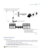
Figure 8
shows the wiring between the battery and the power supply.
Wiring AC power fail
The power supply includes a relay that monitors and signals the loss of AC power. The power fail line is low
during normal operation, and goes high when AC input power is lost.
If this option is used, connect the power supply AC power fail NC and COM terminals to the Power/
Communications Board connector J6, pin 6 (ground) and pin 8 (AC power fail input). See
Figure 8
on page 23.
Wiring low battery detect
The power supply includes a low battery relay to detect and signal a low battery condition (11 VDC or less).
If this option is used, connect the power supply low battery NC and NO terminals to the 20DI Board connector
J2, pins 1 and 2. Install 2K resistors at power supply terminals. See
Figure 8
on page 23.
CAUTION:
Make sure AC input and battery backup power is disconnected prior to installing CPU, reader, DI, and
DO boards.
CAUTION:
Replace battery with lead acid sealed 12 AH only.
Содержание M3000
Страница 1: ...M3000 Installation Manual P N 460630001H 15JUNE11 ...
Страница 10: ...M3000 Installation Manual x ...
Страница 37: ...Chapter 3 Power Communications board 27 Host computer wiring Figure 9 Wiring host computer to first M3000 ...
Страница 39: ...Chapter 3 Power Communications board 29 Figure 11 Wiring modem to M3000 M 5 or serial printer ...
Страница 41: ...Chapter 3 Power Communications board 31 Figure 13 Wiring downstream away from the host using RS 232 ...
Страница 47: ...Chapter 4 PXNplus CPU board 37 Board layout Figure 16 PXNplus CPU board layout ...
Страница 58: ...M3000 Installation Manual 48 Board layout Figure 17 2RP reader board layout ...
Страница 65: ...Chapter 5 Reader processing boards 55 Figure 21 Wiring 2RP to Wiegand Strobed F 2F and supervised F 2F readers ...
Страница 68: ...M3000 Installation Manual 58 Figure 24 Wiring 2RP door strike external relay ...
Страница 72: ...M3000 Installation Manual 62 Board layout Figure 27 2SRP supervised reader board layout ...
Страница 78: ...M3000 Installation Manual 68 Figure 30 Wiring 2SRP to Wiegand F 2F Strobed and Supervised F 2F Readers ...
Страница 82: ...M3000 Installation Manual 72 Figure 19 Wiring 2SRP door alarm contact and exit request ...
Страница 84: ...M3000 Installation Manual 74 Figure 21 Wiring 2SRP door strike external relay ...
Страница 89: ...Chapter 5 Reader processing boards 79 Board layout Figure 24 8RP reader board layout ...
Страница 92: ...M3000 Installation Manual 82 Figure 26 Wiring 8RP to F 2F or Supervised F 2F Readers ...
Страница 94: ...M3000 Installation Manual 84 ...
Страница 97: ...Chapter 6 Optional DI and DO boards 87 Figure 31 20DI board layout ...
Страница 99: ...Chapter 6 Optional DI and DO boards 89 Figure 32 Wiring DI point ...
Страница 101: ...Chapter 6 Optional DI and DO boards 91 Figure 33 16DO board layout ...
Страница 102: ...M3000 Installation Manual 92 Figure 34 16DOR board layout ...
Страница 104: ...M3000 Installation Manual 94 Figure 36 Wiring output device to 16DOR board ...
Страница 152: ...M3000 Installation Manual 142 ...
Страница 156: ...M5 controller Installation Manual 146 Figure 76 Installing ferrite ...
Страница 160: ...M5 controller Installation Manual 150 ...
Страница 172: ...M3000 Installation Manual 162 ...


