Chapter 8
Controller firmware tools
129
Operating eFlash from the command line
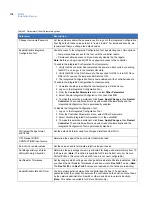
One or more of the arguments listed in
Table 36. eFlash command line arguments
can be included in a
command line.
Note:
If an option is repeated, only the last value is used with the exception of -m and -l, which may be repeated
multiple times. For example, to flash controller id 0 and controller id 2, the entry would be: eflash -m 0 -m 2.
To flash a controller using eFlash from the command line:
1. Log on as
root
and open a terminal window.
2. At the command prompt, enter a command using the following parameters:
eflash -c -m01 -p /cas/flash/eflash -f mspe170.efl
where
m01
is the micro id and
mspe170.efl
is the flash file.
Result:
After the flashing has completed, one of the following messages will be displayed:
Flashing is successful
or
Flashing is unsuccessful. See the log file<filename> for details.
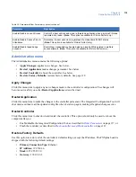
Table 36. eFlash command line arguments
Argument
Description
c
Command line selection option
-p<directory>
Specifies the source directory to search for flash files. This replaces the default directory
of /cas/flash/eflash.
-f<filename>
Specifies a flash file to use for the 5PX controller, instead of the default flash.
-n<filename>
Specifies a flash file to use for the 5PXN controller, instead of the default flash.
-x<number>
Specifies the maximum number of controllers that can be flashed at one time.
-h
Starts the HTML based online help.
-u or -?
Prints the usage message.
-m<micro selection>
Specifies the controller to be flashed. This option can be repeated multiple times.
• To flash all active controllers in the Picture Perfect database, use:
eflash -m a
• To flash a specific controller, use:
eflash -m <microid>
where
<microid>
is the ID of any controller on the line. eFlash adds all other
controllers on the line to the flash list in the correct order.
• To flash a line of controllers, use:
eflash -l <microid>
where
<microid>
is the ID of a controller, such as 0001 that is on the line you want
to flash.
Содержание M3000
Страница 1: ...M3000 Installation Manual P N 460630001H 15JUNE11 ...
Страница 10: ...M3000 Installation Manual x ...
Страница 37: ...Chapter 3 Power Communications board 27 Host computer wiring Figure 9 Wiring host computer to first M3000 ...
Страница 39: ...Chapter 3 Power Communications board 29 Figure 11 Wiring modem to M3000 M 5 or serial printer ...
Страница 41: ...Chapter 3 Power Communications board 31 Figure 13 Wiring downstream away from the host using RS 232 ...
Страница 47: ...Chapter 4 PXNplus CPU board 37 Board layout Figure 16 PXNplus CPU board layout ...
Страница 58: ...M3000 Installation Manual 48 Board layout Figure 17 2RP reader board layout ...
Страница 65: ...Chapter 5 Reader processing boards 55 Figure 21 Wiring 2RP to Wiegand Strobed F 2F and supervised F 2F readers ...
Страница 68: ...M3000 Installation Manual 58 Figure 24 Wiring 2RP door strike external relay ...
Страница 72: ...M3000 Installation Manual 62 Board layout Figure 27 2SRP supervised reader board layout ...
Страница 78: ...M3000 Installation Manual 68 Figure 30 Wiring 2SRP to Wiegand F 2F Strobed and Supervised F 2F Readers ...
Страница 82: ...M3000 Installation Manual 72 Figure 19 Wiring 2SRP door alarm contact and exit request ...
Страница 84: ...M3000 Installation Manual 74 Figure 21 Wiring 2SRP door strike external relay ...
Страница 89: ...Chapter 5 Reader processing boards 79 Board layout Figure 24 8RP reader board layout ...
Страница 92: ...M3000 Installation Manual 82 Figure 26 Wiring 8RP to F 2F or Supervised F 2F Readers ...
Страница 94: ...M3000 Installation Manual 84 ...
Страница 97: ...Chapter 6 Optional DI and DO boards 87 Figure 31 20DI board layout ...
Страница 99: ...Chapter 6 Optional DI and DO boards 89 Figure 32 Wiring DI point ...
Страница 101: ...Chapter 6 Optional DI and DO boards 91 Figure 33 16DO board layout ...
Страница 102: ...M3000 Installation Manual 92 Figure 34 16DOR board layout ...
Страница 104: ...M3000 Installation Manual 94 Figure 36 Wiring output device to 16DOR board ...
Страница 152: ...M3000 Installation Manual 142 ...
Страница 156: ...M5 controller Installation Manual 146 Figure 76 Installing ferrite ...
Страница 160: ...M5 controller Installation Manual 150 ...
Страница 172: ...M3000 Installation Manual 162 ...


