3-37
7.1
95-8533
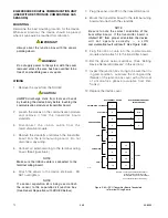
Power Connector, Terminals 1 to 6
24 vdc Power Input
1 — +
2 — –
3 — Shield*
4 — +
5 — –
6 — Shield*
*Shields on power wires are optional unless required
by local codes.
Connect the module power supply to terminals 1 and
2. If additional terminals are required for powering
other devices, these devices should be connected to
terminals 4 and 5. Shields are to be connected to
terminals 3 and 6.
COM Connector, Terminals 1 to 6
LON Terminals
Be sure to observe polarity when wiring the LON.
1 — "A" side of signaling circuit for COM 1
2 — "B" side of signaling circuit for COM 1
4 — "A" side of signaling circuit for COM 2
5 — "B" side of signaling circuit for COM 2
3 & 6 — shield connections.
Channel Connectors, Terminals 1 to 24
Unsupervised Output Ancillary Applications
(Unrelated to Fire Detection/Protection)
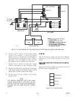
Connect external wiring to the appropriate terminals
on the relay module terminal block. See Figure 3-45.
CONFIGURATION
Setting Relay Module Network Address
One unique network address must be assigned to
each relay module. The address is set by the 8 switch
DIP assembly on the relay module. The address is
binary coded and is the sum of all switches placed in
the “closed” position.
Each discrete point of a relay module has a tag
number and a descriptor for unique identification.
Det-Tronics S
3
Safety System Software is used for
device configuration. The following shows the
minimum software/firmware releases:
CHANNEL 8
CHANNEL 7
CHANNEL 6
CHANNEL 5
CHANNEL 4
CHANNEL 3
CHANNEL 2
CHANNEL 1
COM
6
5
4
3
2
1
COM 2 SHLD
COM 2 B
COM 2 A
COM 1 SHLD
COM 1 B
COM 1 A
SHLD
B
A
SHLD
B
A
LON FROM
PREVIOUS DEVICE
LON TO
NEXT DEVICE
POWER
6
5
4
3
2
1
SHLD
–
+
SHLD
–
+
SHLD
*
–
+
SHLD
*
–
+
24 VDC
INPUT VOLTAGE
24 VDC
INPUT VOLTAGE
EQ3720RM
TO
EARTH
GROUND
C2206
COMMON A
NO B
NC C
COMMON A
NO B
NC C
COMMON A
NO B
NC C
COMMON A
NO B
NC C
COMMON A
NO B
NC C
COMMON A
NO B
NC C
COMMON A
NO B
NC C
COMMON A
NO B
NC C
1
2
3
4
5
6
7
8
9
10
11
12
13
14
15
16
17
18
19
20
21
22
23
24
*
SHIELDS ON POWER WIRES ARE OPTIONAL
UNLESS REQUIRED BY LOCAL CODES.
NOTE: RELAY CONTACTS SHOWN IN REST (DE-ENERGIZED) STATE.
Figure 3-45— Relay Module Wiring Terminal Configuration
Controller Firmware
S3
Revision
Version
Version
A
2.01
2.8.0.0
Содержание DET-TRONICS 95-8533
Страница 1: ...Instructions 95 8533 Eagle Quantum Premier Fire and Gas Detection Releasing System 7 1 9 09 95 8533 ...
Страница 128: ...7 1 95 8533 A 4 Figure A 1 System Drawing 007545 001 ...
Страница 129: ...95 8533 A 5 7 1 Figure A 2 System Drawing 007545 001 ...
Страница 131: ...95 8533 7 1 B 2 Figure B 1 Drawing 007546 001 ...
Страница 132: ...95 8533 7 1 B 3 Figure B 2 Drawing 007546 001 ...
Страница 134: ...95 8533 7 1 C 2 Figure C 1 Drawing 007547 001 ...
Страница 141: ...95 8533 7 1 D 7 Figure D1 System Drawing 007545 001 ...
Страница 143: ...APPENDIX E E 1 95 8533 7 1 ...


