3-17
7.1
95-8533
parity check for the serial port, and Modbus device
address. Software selectable baud rates are
9600,19200, 38400, 57600, 115200 and 230400.
Software selectable parity is None, Odd, and Even.
The controller uses 8 data bits with 1 stop bit.
Port Pinout (3-position terminal block)
60 — A
61 — B
62 — GND
Jumper P28 – RS-485 Termination Jumper
1-2
Terminated 121 ohms (factory setting)
2-3
Unterminated
Transceiver input impedance: 68 kohm
Jumper P29 – RS-485 Ground Fault Monitor
1-2
Enabled
2-3
Disabled (factory setting)
1
P25
3
1
60
61
64
67
62
63
65
66
68
P26
3
P27
1
3
RS-232 Receive LED (Green)
RS-232 Receive LED (Green)
RS-485 Transmit LED (Amber)
RS-485 Transmit LED (Amber)
RS-485 Termination Jumper
P28: RS-485 Termination Jumper
P29: RS-485 Ground Fault
MonitorJumper
A
B
Channel
Indicators
RS-485 Receive LED (Green)
RS-485 Receive LED (Green)
RS-232 Transmit LED
(Amber)
RS-232 Transmit LED (Amber)
LON COM 2
Termination Jumper
LON COM 1
Termination Jumper
P28
1
3
P29
1
3
P12
PORT 4
P11
PORT 3
P10
PORT 2
P
O
R
T
1
EAGLE QUANTUM PREMIER
Safety System Controller
Fire Alarm
Inhibit
Power
Supr
High Gas
Trouble
Cntrl Flt
Lon Fault
Low Gas
Ack
Silence
Out Inhibit
Eagle Quantum Premier
Time & Date
Cancel
Enter
Next
Previous
Reset
Acknowledge Silence
DET
-
TRONICS
®
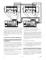
Figure 3-12—Location of Termination Jumpers, Communication Indicator LEDs and Communication Ports
Содержание DET-TRONICS 95-8533
Страница 1: ...Instructions 95 8533 Eagle Quantum Premier Fire and Gas Detection Releasing System 7 1 9 09 95 8533 ...
Страница 128: ...7 1 95 8533 A 4 Figure A 1 System Drawing 007545 001 ...
Страница 129: ...95 8533 A 5 7 1 Figure A 2 System Drawing 007545 001 ...
Страница 131: ...95 8533 7 1 B 2 Figure B 1 Drawing 007546 001 ...
Страница 132: ...95 8533 7 1 B 3 Figure B 2 Drawing 007546 001 ...
Страница 134: ...95 8533 7 1 C 2 Figure C 1 Drawing 007547 001 ...
Страница 141: ...95 8533 7 1 D 7 Figure D1 System Drawing 007545 001 ...
Страница 143: ...APPENDIX E E 1 95 8533 7 1 ...


