3-29
7.1
95-8533
Two-Wire Smoke Detectors
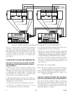
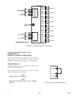
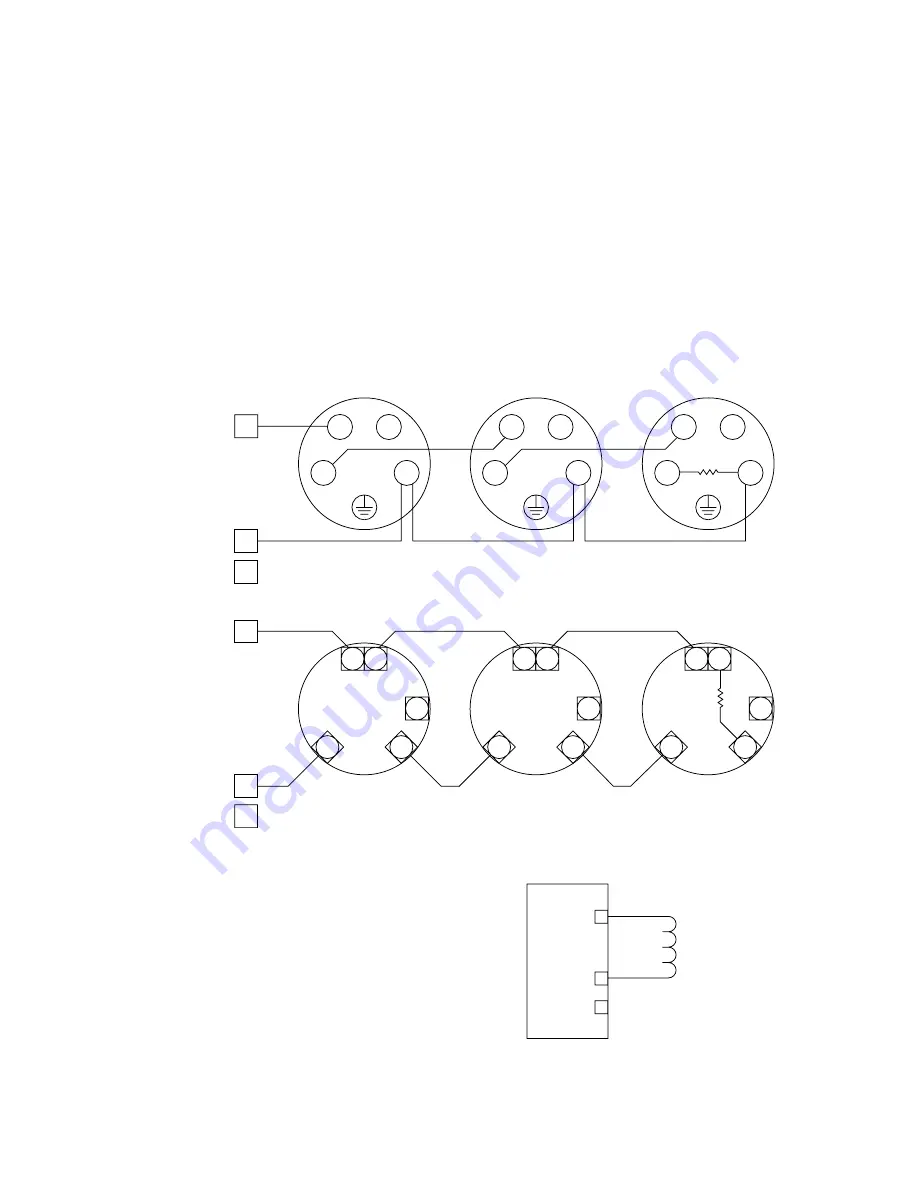
The EDIO supports 2-wire devices from Kidde-Fenwal
and Apollo. Figure 3-31 shows the wiring for Apollo
detectors connected to EDIO Channel 1 through
terminals 1 and 2.
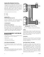
Figure 3-32 shows the typical wiring for Kidde-Fenwal
detectors connected to the EDIO through Channel 1
using terminals 1 and 2.
The EDIO supports either brand of detection products,
however, mixing brands is not supported on either a
single channel or module.
IMPORTANT
No more than 15 devices can be connected per
channel.
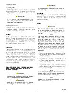
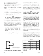
Unsupervised Output
Connect external system wiring to the appropriate
terminals on the terminal block. See Figure 3-33.
No connection should be made to “+ Supply”
terminal.
IN
OUT
UNUSED
OUT
OUT
IN
IN
A2283
1
-R
L1
L2
L1
L1
-R
L1
L2
L1
-R
L1
L2
2
3
+ SUPPLY A
IN–/OUT+ B
COMMON C
EOL
RESISTOR
5 K
Ω
A2284
1
2
3
UNUSED
3
6
7
1
2
3
6
7
1
2
3
6
7
1
2
+ SUPPLY A
IN–/OUT+ B
COMMON C
EOL
RESISTOR
5 K
Ω
Figure 3-31—Apollo 2-Wire Devices
Figure 3-32—Kidde-Fenwal 2-Wire Devices
+ SUPPLY A
IN– / OUT+ B
COMMON C
1
2
3
NOTE: SHUNT/FLYBACK DIODES DO NOT NEED
TO BE INSTALLED ON THE FIELD DEVICE.
CIRCUIT PROTECTION IS PROVIDED
WITHIN THE EDIO MODULE.
A2321
Figure 3-33—Unsupervised Output Configuration
Содержание DET-TRONICS 95-8533
Страница 1: ...Instructions 95 8533 Eagle Quantum Premier Fire and Gas Detection Releasing System 7 1 9 09 95 8533 ...
Страница 128: ...7 1 95 8533 A 4 Figure A 1 System Drawing 007545 001 ...
Страница 129: ...95 8533 A 5 7 1 Figure A 2 System Drawing 007545 001 ...
Страница 131: ...95 8533 7 1 B 2 Figure B 1 Drawing 007546 001 ...
Страница 132: ...95 8533 7 1 B 3 Figure B 2 Drawing 007546 001 ...
Страница 134: ...95 8533 7 1 C 2 Figure C 1 Drawing 007547 001 ...
Страница 141: ...95 8533 7 1 D 7 Figure D1 System Drawing 007545 001 ...
Страница 143: ...APPENDIX E E 1 95 8533 7 1 ...


