7.1
3-26
95-8533
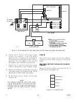
2. Connect the 24 VDC output to the Redundancy
Module. (Redundant “+” and “–” power supply
terminals are connected internally.)
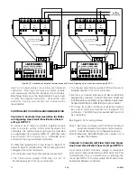
3. To ensure compliance with NFPA 72, primary and
secondary power supplies shall be monitored for
the presence of voltage at the point of connection
to the system. Connect the power supply unit for
preferred preventive function monitoring. Refer to
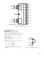
Figure 3-24 for an example of power supply relays
wired in series for power monitoring.
For USCG Approved System monitoring details,
refer to Appendix D.
NOTe
For additional information, refer to the power
supply manufacturer’s documents provided with
the support documentation received with the
eagle Quantum Premier system.
STARTUP
Turn on the power supply and allow the voltage to
stabilize. Verify the output voltage and adjust as
needed. Refer to "EQP2120PS(–B) Power Supplies" in
the Specifications section of this manual.
IMPORTANT!
The output voltage is adjustable. An even current
distribution must be ensured by precisely setting
all power supply units that are operated in
parallel to the same output voltage ±10 mV.
IMPORTANT!
To ensure symmetrical current distribution it is
recommended that all cable connections from all
power supply units/diode redundancy modules
to the power distribution bus are the same length
and have the same cross section.
TO EDIO
L
N
–
–
+
+
DC
OK
13
14
PS n
PHOENIX
QUINT-PS-100-
240AC/24DC/20A
L
N
–
–
+
+
DC
OK
13
14
PS 1
PHOENIX
QUINT-PS-100-
240AC/24DC/20A
L
N
–
–
+
+
DC
OK
13
14
PS
PHOENIX
QUINT-PS-100-
240AC/24DC/20A
L
N
–
–
+
+
DC
OK
13
14
PS
PHOENIX
QUINT-PS-100-
240AC/24DC/20A
B2438
Figure 3-24—Power Supply Relays Wired in Series for Trouble Monitoring (up to 16 Power Supplies)
Содержание DET-TRONICS 95-8533
Страница 1: ...Instructions 95 8533 Eagle Quantum Premier Fire and Gas Detection Releasing System 7 1 9 09 95 8533 ...
Страница 128: ...7 1 95 8533 A 4 Figure A 1 System Drawing 007545 001 ...
Страница 129: ...95 8533 A 5 7 1 Figure A 2 System Drawing 007545 001 ...
Страница 131: ...95 8533 7 1 B 2 Figure B 1 Drawing 007546 001 ...
Страница 132: ...95 8533 7 1 B 3 Figure B 2 Drawing 007546 001 ...
Страница 134: ...95 8533 7 1 C 2 Figure C 1 Drawing 007547 001 ...
Страница 141: ...95 8533 7 1 D 7 Figure D1 System Drawing 007545 001 ...
Страница 143: ...APPENDIX E E 1 95 8533 7 1 ...

