7.1
95-8533
4-7
Note
If multiple alarms are present, “Acknowledging”
will silence the audible alarms.
CONTROLNET STATUS INDICATORS
(Optional)
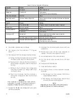
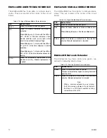
The optional ControlNet status indicator LEDs function
as follows: (see Table 4-3)
Steady - The indicator is on continuously in the
defined state.
Alternating - The two indicators alternate between the
two defined states at the same time (applies to both
indicators viewed together). The two indicators are
always in opposite states, out of phase.
Flashing - The indicator alternates between the two
defined states (applies to each indicator viewed
independent of the other). If both indicators are
flashing, they must flash together, in phase.
SEQUENCE OF EVENTS DURING A
CONFIGURATION DATA DOWNLOAD
During a configuration download, the controller
receives configuration data that is stored into flash
memory. During the download process, the controller
halts normal operation and resets a number of
controller functions. Items affected and displayed
during a configuration data download are listed in the
following steps:
1. Halt the static logic and user logic programs.
2. Ignore field device LON communications.
However, the controller continues to generate the
LON heartbeat.
3. Silence the Controller’s audible annunciator.
4. Initiate a Trouble condition that is signaled by the
amber Trouble LED and relay.
5. Clear all Alarm and Fault events.
6. De-energize all 8 Controller relays.
7. Ignore Modbus communication.
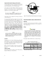
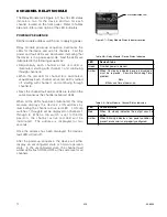
0.5 SEC
0.5 SEC
1.5 SEC
FIRE
ALARM
0.5 SEC
0.5 SEC
3.0 SEC
HIGH/LOW
GAS
0.5 SEC
5.0 SEC
TROUBLE
0.1 SEC
0.1 SEC
2.0 SEC
SUPERVISORY
B1855
Figure 4-4—Tone Pattern for Controller Buzzer
Содержание DET-TRONICS 95-8533
Страница 1: ...Instructions 95 8533 Eagle Quantum Premier Fire and Gas Detection Releasing System 7 1 9 09 95 8533 ...
Страница 128: ...7 1 95 8533 A 4 Figure A 1 System Drawing 007545 001 ...
Страница 129: ...95 8533 A 5 7 1 Figure A 2 System Drawing 007545 001 ...
Страница 131: ...95 8533 7 1 B 2 Figure B 1 Drawing 007546 001 ...
Страница 132: ...95 8533 7 1 B 3 Figure B 2 Drawing 007546 001 ...
Страница 134: ...95 8533 7 1 C 2 Figure C 1 Drawing 007547 001 ...
Страница 141: ...95 8533 7 1 D 7 Figure D1 System Drawing 007545 001 ...
Страница 143: ...APPENDIX E E 1 95 8533 7 1 ...


