3-7
7.1
95-8533
Shield Grounding
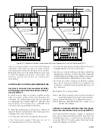
Two shield ground terminals are provided inside the
junction box of each device, and also at the System
Controller. Connect shield ends to the terminals
provided (not to each other) inside the junction box.
CAUTION!
Insulate the shields to prevent shorting to the
device housing or to any other conductor. Refer
to Appendix C for eMC Directive requirements.
Junction Box Grounding
All junction boxes must be electrically connected to
earth ground.
Response Time vs. System Size
When designing a system, it is important to realize
that by increasing the number of nodes (devices) on
the communication loop, the amount of time required
for a status change message from a detection device
to reach the System Controller also increases.
The System Controller requires a specific length of
time to process each bit of information that is
transferred along the communication loop. As the
number of nodes increases, so does the amount of
data being processed as well as the time required for
processing by the Controller.
If the fastest possible communication response time is
an important criteria for a large system, it is
recommended that the number of nodes on an
individual loop be kept as small as possible. Consider
using multiple controllers with fewer nodes per loop.
Moisture Damage Protection
Moisture can adversely affect the performance of
electronic devices. It is important to take proper
precautions during system installation to ensure that
moisture will not come in contact with electrical
connections or components.
In applications where the network wiring is installed in
conduit, the use of watertight conduit seals, drains,
breathers, or equivalent is recommended to prevent
damage caused by condensation within the conduit.
Electrostatic Discharge
An electrostatic charge can build up on the skin and
discharge when an object is touched. ALWAYS use
caution when handling devices, taking care not to
touch the terminals or electronic components.
CAUTION!
ALWAYS discharge static charges from hands
before handling electronic devices or touching
device terminals. Many devices contain
semiconductors that are susceptible to damage
by electrostatic discharge.
NOTe
For more information on proper handling, refer to
Det-Tronics Service Memo form 75-1005.
GROUND FAULT MONITOR (GFM)
INSTALLATION
Mounting
The GFM is a DIN rail mountable device designed to be
mounted in the same enclosure as the EQP controller.
Wiring
1. Connect power wiring from the EQP controller power
terminals 1 and 2 to the GFM terminals 1 and 2.
2. Connect power wiring from the GFM terminals 3 and
4 to the EQP controller power terminals 3 and 4.
3. Connect earth ground to terminal 5 or 10.
4. Connect the relay contacts as required.
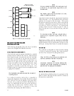
Refer to Figure 3-1 for terminal block identification.
6
7
8
9
10
COMMON
NO
NC
N/C
RELAY
SPARE
1
2
3
4
5
+
+
–
–
EARTH
GROUND
+
+
–
–
EARTH
GROUND
24 VDC
INPUT VOLTAGE
NOTE: RELAY CONTACTS ARE SHOWN IN THE REST STATE,
NO POWER APPLIED. RELAY IS ENERGIZED WITH
POWER APPLIED AND NO GROUND FAULT
(TERMINALS 6 & 7 CLOSE, TERMINALS 6 & 8 OPEN).
Figure 3-1—Terminal Configuration for Ground Fault Monitor
Содержание DET-TRONICS 95-8533
Страница 1: ...Instructions 95 8533 Eagle Quantum Premier Fire and Gas Detection Releasing System 7 1 9 09 95 8533 ...
Страница 128: ...7 1 95 8533 A 4 Figure A 1 System Drawing 007545 001 ...
Страница 129: ...95 8533 A 5 7 1 Figure A 2 System Drawing 007545 001 ...
Страница 131: ...95 8533 7 1 B 2 Figure B 1 Drawing 007546 001 ...
Страница 132: ...95 8533 7 1 B 3 Figure B 2 Drawing 007546 001 ...
Страница 134: ...95 8533 7 1 C 2 Figure C 1 Drawing 007547 001 ...
Страница 141: ...95 8533 7 1 D 7 Figure D1 System Drawing 007545 001 ...
Страница 143: ...APPENDIX E E 1 95 8533 7 1 ...


