7.1
3-16
95-8533
Connector P2, Terminals 5 to12 —
Unsupervised Digital Input Channels 1 to 4
Connector P3, Terminals 13 to 20 —
Unsupervised Digital Input Channels 5 to 8
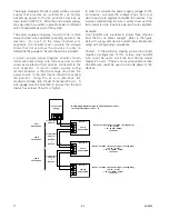
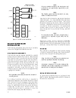
See Figure 3-10 for example. Only channel 1 is shown
in Figure 3-10. The information is typical for channels
2-8.
Connector P4, Terminals 21 to 32 —
Unsupervised Relay Output Channels 1 to 4
Connector P5, Terminals 33 to 44 —
Unsupervised Relay Output Channels 5 to 8
See Figure 3-11 for example. Only channel 1 is shown
in Figure 3-11. The information is typical for channels
2-8.
NOTe
Channel software configurations include all
panel indicator functions to automatically mimic
the controller front panel indicators.
Connector P6, Terminals 45, 46 & 47 —
Trouble Relay
The Trouble relay is not configurable. In the normal
condition, the relay coil is energized, closing the N.O.
contact (terminals 45-46) and opening the N.C.
contact (terminals 45-47). The relay coil is
de-energized in the trouble condition.
Connector P7, Terminals 48 to 53 —
LON Signaling Line Circuit Terminals
The LON loop is wired so that the controller’s LON
COM 1 is connected to the field device’s COM 2
connection. The field device’s COM 1 is wired to the
next device’s COM 2 connection. This continues
through the last field device on the loop. The last field
device’s COM 1 is then wired back to the Controller’s
COM 2 connection. LON A and B polarities must be
maintained throughout the loop (i.e., always wire A to
A and B to B between the devices).
Port Pinout (6-position connection terminal block)
48 — COM 1 shield connection
49 — "B" side of signaling circuit for COM 1
50 — "A" side of signaling circuit for COM 1
51 — COM 2 shield connection
52 — "B" side of signaling circuit for COM 2
53 — "A" side of signaling circuit for COM 2
NOTe
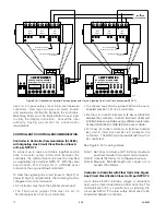
Refer to Figure 3-12 for location of termination
jumpers.
Jumper P25 – LON COM 1 Termination
1-2
COM 1 Terminated (factory setting)
2-3
COM 1 Unterminated (Redundancy)
Jumper P26 – LON COM 2 Termination
1-2
COM 2 Terminated (factory setting)
2-3
COM 2 Unterminated (Redundancy)
Connector P8, Terminals 54, 55 & 56 , Port 1—
RS-485 Modbus RTU Master/Slave
Configuration data downloaded into the controller
configures the serial interface transmission baud rate,
parity check for the serial port, and Modbus device
address. Software selectable baud rates are 2400,
4800, 9600,19200, 38400, 57600, and 115200.
Software selectable parity is None, Odd, and Even.
The controller uses 8 data bits with 1 stop bit.
Port Pinout (3-position terminal block)
54 — GND
55 — B
56 — A
Jumper P27 – RS-485 Termination Jumper
1-2
Unterminated
2-3
Terminated 121 ohms (factory setting)
Transceiver input impedance: 68 kohm
Connector P9, Terminals 57, 58 & 59 —
RS-232 Serial Interface or S3 Configuration Port
Configuration data downloaded into the controller
configures the serial interface transmission baud rate
and parity check for the serial port. Software
selectable baud rates are 2400, 4800, 9600,19200,
38400, 57600, and 115200 (factory default is 115200).
Software selectable parity is None, Odd, and Even.
The controller uses 8 data bits with 1 stop bit.
Port Pinout (3-position terminal block)
57 — GND
58 — RXD
59 — TXD
Connector P10, Terminals 60, 61 & 62, Port 2–
RS-485 Modbus RTU Master/Slave
Configuration data downloaded into the controller
configures the serial interface transmission baud rate,
Содержание DET-TRONICS 95-8533
Страница 1: ...Instructions 95 8533 Eagle Quantum Premier Fire and Gas Detection Releasing System 7 1 9 09 95 8533 ...
Страница 128: ...7 1 95 8533 A 4 Figure A 1 System Drawing 007545 001 ...
Страница 129: ...95 8533 A 5 7 1 Figure A 2 System Drawing 007545 001 ...
Страница 131: ...95 8533 7 1 B 2 Figure B 1 Drawing 007546 001 ...
Страница 132: ...95 8533 7 1 B 3 Figure B 2 Drawing 007546 001 ...
Страница 134: ...95 8533 7 1 C 2 Figure C 1 Drawing 007547 001 ...
Страница 141: ...95 8533 7 1 D 7 Figure D1 System Drawing 007545 001 ...
Страница 143: ...APPENDIX E E 1 95 8533 7 1 ...

