7.1
3-28
95-8533
Connector P4, Terminals 13 to 24
Terminals A, B & C
Channels 5 to 8 Input / Output Terminals
Refer to individual wiring configurations for terminal
descriptions. Only channel 1 is shown in each
diagram. The information is typical for channels 2-8.
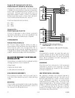
Unsupervised Input
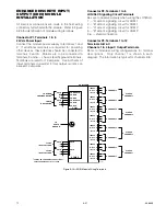
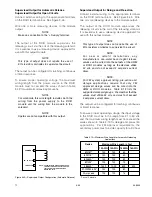
Connect external system wiring to the appropriate
terminals on the terminal block. See Figure 3-26.
The input to the EDIO consists of one or more normally
open or normally closed switches. An EOL resistor is
not required.
Make no connection to “+ Supply” terminal.
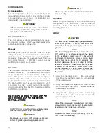
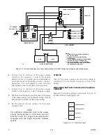
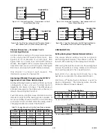
Supervised Input (IDC) Open Circuit Supervision
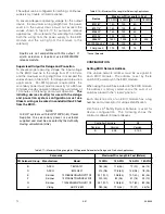
Connect external system wiring to the appropriate
terminals on the terminal block. For Class B, Style B
wiring, see Figure 3-27. For Class A, Style D wiring,
see Figure 3-28. Note that two channels are used for
one circuit.
The input to the EDIO module consists of one or more
normally open switches, with a 10 K ohm, 1/4 watt
EOL resistor in parallel across the last switch.
Make no connection to “+ Supply” terminal.
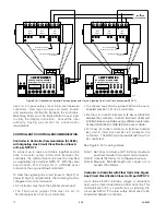
Supervised Input Open and Short Circuit Supervision
Connect external system wiring to the appropriate
terminals on the terminal block. For Class B, Style C
wiring, see Figure 3-29. For Class A, Style E wiring,
see Figure 3-30. Note that two channels are used for
one circuit.
The input to the EDIO module consists of normally
open switches, with a 10 K ohm, 1/4 watt EOL resistor
in parallel across the return channel, and a 3.3 K ohm,
1/4 watt resistor in series with each switch.
NOTe
If using more than one switch, the first active
condition (switch closed) must be latched. Any
subsequent closed switch will indicate a short
circuit fault condition.
Make no connection to “+ Supply” terminal.
Input — Deluge and Pre-Action
The initiating device circuit(s) for use with the deluge
and pre-action system configuration must use Class A
wiring or be wired within 20 feet and in conduit from the
EDIO.
+ SUPPLY A
IN– / OUT+ B
COMMON C
1
2
3
EOL
RESISTOR
10 K
Ω
C2091
Figure 27—Supervised Input Configuration – Class B, Style B
+ SUPPLY A
IN– / OUT+ B
COMMON C
1
2
3
EOL
RESISTOR
10 K
Ω
INLINE
RESISTOR
3.3 K
Ω
C2092
Figure 3-29—Supervised Input Configuration (Opens and Shorts) –
Class B, Style C
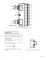
+ SUPPLY A
IN– / OUT+ B
COMMON C
1
2
3
+ SUPPLY A
IN– / OUT+ B
COMMON C
4
5
6
B2291
EOL
RESISTOR
10 K
Ω
Figure 3-28—Supervised Input Configuration – Class A, Style D
+ SUPPLY A
IN– / OUT+ B
COMMON C
1
2
3
+ SUPPLY A
IN– / OUT+ B
COMMON C
4
5
6
B2292
INLINE
RESISTOR
3.3 K
Ω
EOL
RESISTOR
10 K
Ω
Figure 3-30—Supervised Input Configuration (Opens and Shorts) –
Class A, Style E
+ SUPPLY A
IN– / OUT+ B
COMMON C
1
2
3
C2090
Figure 3-26—Unsupervised Input Configuration
Содержание DET-TRONICS 95-8533
Страница 1: ...Instructions 95 8533 Eagle Quantum Premier Fire and Gas Detection Releasing System 7 1 9 09 95 8533 ...
Страница 128: ...7 1 95 8533 A 4 Figure A 1 System Drawing 007545 001 ...
Страница 129: ...95 8533 A 5 7 1 Figure A 2 System Drawing 007545 001 ...
Страница 131: ...95 8533 7 1 B 2 Figure B 1 Drawing 007546 001 ...
Страница 132: ...95 8533 7 1 B 3 Figure B 2 Drawing 007546 001 ...
Страница 134: ...95 8533 7 1 C 2 Figure C 1 Drawing 007547 001 ...
Страница 141: ...95 8533 7 1 D 7 Figure D1 System Drawing 007545 001 ...
Страница 143: ...APPENDIX E E 1 95 8533 7 1 ...


