7.1
3-22
95-8533
CONFIGURATION
S3 Configuration
The S3 configuration software is used to configure the
redundant controllers. A check box on the controller
configuration screen must be enabled and
downloaded to the controllers.
IMPORTANT
If the controllers have not been configured for
redundancy via the S3 configuration software,
redundancy will not function.
Controller Addresses
The LON addresses are pre-determined and cannot
be adjusted. Address 1 and 2 have been reserved for
a redundant controller configuration.
Modbus
Modbus ports on each controller share the serial
settings including baud rate and address. Controllers
in standby mode don’t respond to or issue Modbus
messages. This allows for transparent switching on a
multi-drop network. If RS-232 is used, a relay
switching mechanism can be used.
ControlNet
The ControlNet interface on each controller will have
different addresses. This allows both controllers to
reside on the same ControlNet network at the same
time. The primary controller uses the configured
address while the standby assumes an address 1
higher than the primary controller. Application logic in
the attached PLC must be used to determine which
controller has the correct output information.
Information coming from the PLC should be written to
both Premier Controllers.
EQ21XXPS SERIES POWER SUPPLY
AND POWER SUPPLY MONITOR
INSTALLATION
WARNING!
ALWAYS follow all safety notes and instructions
when installing power supply or batteries!
WARNING!
Make sure a.c. power is OFF at main a.c. breaker
before beginning power supply installation!
IMPORTANT!
Power supplies require unrestricted air flow for
proper cooling.
MOUNTING
Mount the power supply monitor in a Nationally
Recognized Test Laboratory (NRTL) labeled
enclosure. Refer to the “Specifications” section for
mounting dimensions.
WIRING
CAUTION!
The power supply should be properly connected
to an earth ground! A ground wire MUST be
connected to the power supply units’s case
ground!
NOTe
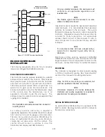
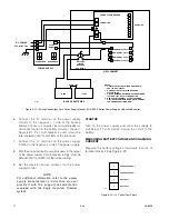
The Power Supply Monitor uses two of the four
DIP switches to select an appropriate fault level
for the installation. See Figure 3-18. The unit will
fault when the batteries source a current level
higher than the threshold for 20 seconds. The
fault will clear when the current drops to half the
level for 20 seconds. The current level selection
is based on the minimum current draw of the
attached equipment. The selected value must be
less than the actual minimum current draw for
the system.
1. Verify that the input source is the same voltage
and frequency as that marked on the nameplate
of the power supply.
2. Verify that transformer taps are set for the correct
a.c. input. (Input tap setting is located inside the
power supply enclosure.)
3. Verify that the supply power wire size and fusing
are adequate for the current indicated on the
power supply nameplate.
NOTe
Consult the power supply manufacturer’s instruction
manual provided with the support documentation
received with the eagle Quantum System.
NOTe
Required Overload Current is usually equal to
15% of the nominal rating.
Содержание DET-TRONICS 95-8533
Страница 1: ...Instructions 95 8533 Eagle Quantum Premier Fire and Gas Detection Releasing System 7 1 9 09 95 8533 ...
Страница 128: ...7 1 95 8533 A 4 Figure A 1 System Drawing 007545 001 ...
Страница 129: ...95 8533 A 5 7 1 Figure A 2 System Drawing 007545 001 ...
Страница 131: ...95 8533 7 1 B 2 Figure B 1 Drawing 007546 001 ...
Страница 132: ...95 8533 7 1 B 3 Figure B 2 Drawing 007546 001 ...
Страница 134: ...95 8533 7 1 C 2 Figure C 1 Drawing 007547 001 ...
Страница 141: ...95 8533 7 1 D 7 Figure D1 System Drawing 007545 001 ...
Страница 143: ...APPENDIX E E 1 95 8533 7 1 ...


