95-8533
7.1
D-3
QUINT-DIODE/40 REDUNDANCY MODULE
number of units:
8 (2 Power Supplies can be connected to each module) max
input voltage:
24.5….28.0 Vdc
IMPORTANT
The output voltage is adjustable. An even current distribution must be ensured by precisely setting all power
supply units that are operated in parallel to the same output voltage ±10 mV.
IMPORTANT
To ensure symmetrical current distribution it is recommended that all cable connections from all power supply
units/diode redundancy modules to the power distribution bus are the same length and have the same cross
section.
POWER REQUIREMENT—
Refer to Section 6 of this manual and individual device manuals for details.
NOTE
The Power Supply and Diode Redundancy Module electrical specifications for EQP marine applications
represent a reduction in the rating range with respect to that specified by the manufacturer. The manufacturer’s
published electrical specifications may be viewed as reference only.
TEMPERATURE AND HUMIDITY RANGE—
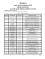
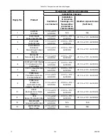
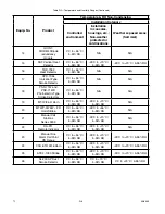
See Table D-2 for details.
NOTE
The operating temperature and relative humidity specification of EQP System components including Power
Supply and Diode Redundancy Module in EQP marine applications represent a reduction in the rating range
for some components and an increase in the rating range for other components with respect to that specified
by their manufacturers. The manufacturer’s published operating temperature and relative humidity specifications
may be viewed as reference only.
INSTALLATION—
The EQP2120PS-B Power Supply and Diode Redundancy Module are Panel mounted and intended to be
mounted within the same cabinet as the EQ300X Controller of the EQP System.
note: ensure sufficient
convection
. Refer to Phoenix Contact manual form 10031-04-en (current issue 12/05) for additional installation
and mounting details. For other EQP System components installation, operation and maintenance refer to
appropriate sections of this manual and to individual device manuals.
NOTE
SHCS # 10-24 SST screws are recommended for the Power Supply and Diode Redundancy Module panel
mounting.
NOTE
Terminal End Brackets DEC P/N 000133-517 are recommended for use with EQ3701(2)(3)0D (DIN rail mount)
and EQ2220GFM Modules.
POWER SUPPLY SUPERVISION—
The EQP2120PS-B Power Supply shall be monitored for Trouble. The power supply provides an internal relay
contact DC OK signal output, floating. All power supply unit relay contacts shall be connected in series and
connected to the EQ3730EDIO input. A Trouble signal will be initiated in case of a power supply failure. The
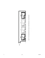
Trouble signal will not identify the specific power supply unit that failed. See Figure D-2 for connecting diagram.
Содержание DET-TRONICS 95-8533
Страница 1: ...Instructions 95 8533 Eagle Quantum Premier Fire and Gas Detection Releasing System 7 1 9 09 95 8533 ...
Страница 128: ...7 1 95 8533 A 4 Figure A 1 System Drawing 007545 001 ...
Страница 129: ...95 8533 A 5 7 1 Figure A 2 System Drawing 007545 001 ...
Страница 131: ...95 8533 7 1 B 2 Figure B 1 Drawing 007546 001 ...
Страница 132: ...95 8533 7 1 B 3 Figure B 2 Drawing 007546 001 ...
Страница 134: ...95 8533 7 1 C 2 Figure C 1 Drawing 007547 001 ...
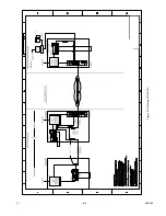
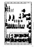
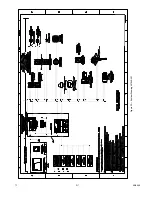
Страница 141: ...95 8533 7 1 D 7 Figure D1 System Drawing 007545 001 ...
Страница 143: ...APPENDIX E E 1 95 8533 7 1 ...


