7.1
3-12
95-8533
WARNING!
If the installation uses catalytic type combustible
gas sensors, it is imperative that lubricants
containing silicone not be used, since they will
cause irreversible damage to the sensor.
5. Install the communication module in the device
enclosure.
NOTe
Be sure the ribbon cable is properly connected.
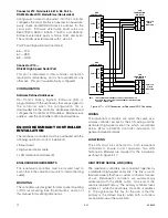
6. Set the node address for the device. (See “Setting
Device Network Addresses” in this section)
When configuring the EQ22xxIDCGF, its “device
type” should be configured as an initiating device
circuit (IDC).
Both inputs must be configured for a trouble
condition.
Circuit 1 –
“Open” indicates a –24 VDC ground
fault condition. “Active” indicates a +24
VDC ground fault condition.
Circuit 2 –
“Active” indicates a loss of AC input
power.
“Open” indicates a loss of battery
power.
7. Place the cover on the enclosure and tighten until
snug. DO NOT over tighten.
EQ22xxIDCSC SERIES INITIATING DEvICE
CIRCUIT SHORT CIRCUIT
(Not FM Approved)
The following paragraphs describe how to properly
install and configure the EQ22xxIDCSC Initiating
Device Circuit Short Circuit.
Mounting
The device should be securely mounted to a vibration
free surface. (See “Specifications” in this manual for
device dimensions.
Wiring
CAUTION!
The enclosure should be electrically connected
to earth ground.
1. Remove the cover from the device enclosure.
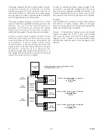
2. Remove the communication module from the
junction box. Connect external wiring to the
appropriate terminals on device terminal block.
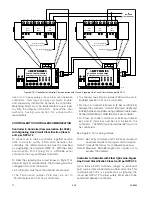
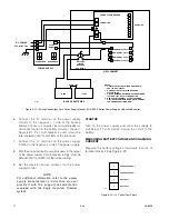
(See Figure 3-4 for terminal block location and
Figure 3-7 for terminal identification.) The input to
the IDCSC consists of a normally open switch with
a 3.3k ohm series resistor, and a 10K ohm, 1/4
watt EOL resistor in parallel across the switch.
NOTe
An eOL resistor must be installed on both IDCSC
inputs (including unused inputs). Wiring
impedance must not exceed 500 ohms. A 3.3K
ohm resistor must be installed in series with the
switch. For correct operation, only one switch
per input can be connected.
3. Check wiring to ensure that ALL connections have
been properly made.
4. Install the communication module in the device
enclosure.
5. Inspect the enclosure O-ring to be sure that it is in
good condition. Lubricate the O-ring and the
threads of the enclosure cover to ease both
installation and future removal of the cover.
NOTe
The recommended lubricant is a silicone free
grease available from Detector electronics.
NOTe
Be sure the ribbon cable is properly connected.
6. Set the node address for the device. (See “Setting
Device Network Addresses” in this section.)
7. Place the cover on the enclosure and tighten until
snug. Do not over tighten.
Содержание DET-TRONICS 95-8533
Страница 1: ...Instructions 95 8533 Eagle Quantum Premier Fire and Gas Detection Releasing System 7 1 9 09 95 8533 ...
Страница 128: ...7 1 95 8533 A 4 Figure A 1 System Drawing 007545 001 ...
Страница 129: ...95 8533 A 5 7 1 Figure A 2 System Drawing 007545 001 ...
Страница 131: ...95 8533 7 1 B 2 Figure B 1 Drawing 007546 001 ...
Страница 132: ...95 8533 7 1 B 3 Figure B 2 Drawing 007546 001 ...
Страница 134: ...95 8533 7 1 C 2 Figure C 1 Drawing 007547 001 ...
Страница 141: ...95 8533 7 1 D 7 Figure D1 System Drawing 007545 001 ...
Страница 143: ...APPENDIX E E 1 95 8533 7 1 ...

