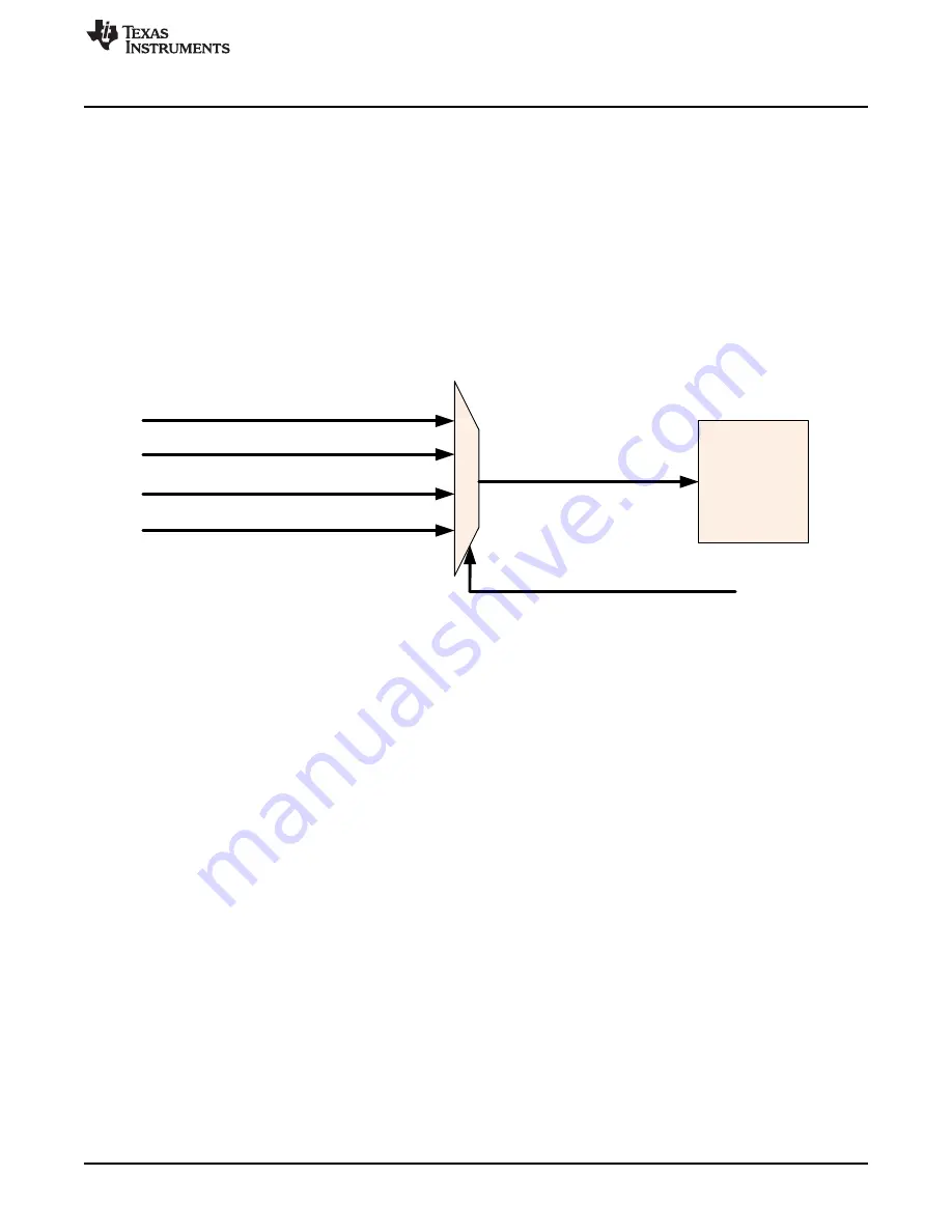
DPWM0 IDE_EN
DPWM1 IDE_EN
DPWM2 IDE_EN
DPWM3 IDE_EN
FILTERx_PER_SEL
FILTERx_IDE_EN
FILTERx
IDE / DCM Detection Control
233
SNIU028A – February 2016 – Revised April 2016
Copyright © 2016, Texas Instruments Incorporated
Fault Mux
In discontinuous mode, the on time(duty) for the sync FET (Db) is proportional to the DPWMA on-time
(Da). The multiplying factor depends on the topology, the circuit configuration and on Vin and Vout. This
multiplying factor needs to be frequently calculated by firmware and placed in the IDE_KD register.
FaultMuxRegs.IDECTRL.bit.IDE_KD = kd_value;
IDE must also be enabled in the DPWM module:
Dpwm1Regs.DPWMCTRL2.bit.IDE_DUTY_B_EN = 1; //enable ide
Db is calculated by Da (Filter Duty) times IDE_KD. KD is an unsigned value with 4 integer bits and 9
fractional bits. For example, a 0b0001.000000000 would equate to a multiplier of 1 (“0b” signifies binary,
and the “.” is used to divide the fractional from the integer part). This would correspond to a hex value of
0x200. For this value of Kd, Db would be exactly the same as Da. There is only one IDE_KD register, but
each Filter can can calculate using the KD. Each Filter’s output of the IDE value is controlled by the
IDE_EN bit in a DPWM module. The DPWM module is selected by the
LoopMux.FILTERMUX.bit.FILTERx_PER_SEL bitfield as shown below:
Figure 6-4.
Normally FILTERx_PER_SEL will already be pointing at the right Filter, because it is also used to provide
the period for the Filter to use in calculating the duty value.
In some cases, however, for example where KCOMP is used instead of period, it is still necessary to set
FILTERx_PER_SEL so that IDE_EN can be multiplexed properly.
Note also that IDE_EN still needs to be set on any DPWM which is using IDE, even though that DPWM
may not be providing IDE_EN to the Filter. If IDE_EN is not set, the normal dead times will be used to
control DPWMB.
The IDECTRL register also contains a means to detect DCM. As mentioned before, in continuous mode,
the sync FET is on for the entire time that DPWMA is off. So Db = 1-Da. In discontinuous mode, Db < 1-
Da. So the DCM detection logic triggers an interrupt when Db < 1-Da. Hysteresis is provided to prevent
the interrupt from triggering repeatedly when steady state is close to the boundary between continuous
and discontinuous. This is done with the DCM_LIMIT_H and DCIM_LIMIT_L registers.
The DCM_DETECT bit is set when:
Db < ((1-Da) - DCIM_LIMIT_L
(3)
It is reset when:
Db > ((1-Da) + DCIM_LIMIT_H
(4)
The DCM_DETECT bit can be monitored in the FAULTMUXRAWSTAT register. The status of the interrupt
can be read in the FAULTMUXINTSTAT register. The interrupt is enabled by DCM_INT_EN in the
IDECTRL register.


