3
ArbConnection
The Control Panels
3-25
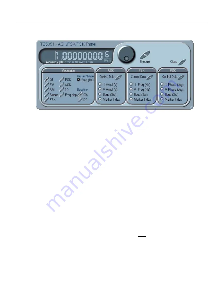
Figure
3-16, the ASK/FSK/PSK Modulation Panel
FSK
Control Data
The Control Data button in the FSK group provides access to the
data string that controls the sequence of base frequency and shifted
frequency. It contains a list of “0” and “1” and the output will
repeatedly follow the frequency shift keying sequence in the same
order as programmed.
“0/1” Frequency
In FSK, the carrier waveform (CW) has two frequencies: an initial
frequency level which is set by the “0” Frequency parameter and
shifted frequency which is set by the “1” Frequency. The control
data table has a list of “0” and “1” values that flag when the
frequency shifts from base to shifted frequency.
Baud
The baud parameter sets the rate of which the generator steps
through the sequence of the FSK Control Data bits.
Marker Index
The marker setting programs a specific step (index) in the control
data string to output a pulse at the SYNC output connector. The
SYNC State button must be turned on to generate the FSK marker
output.
PSK
Control Data
The Control Data button in the PSK group provides access to the
data string that controls the sequence of base phase and shifted
phase. It contains a list of “0” and “1” and the output will repeatedly
follow the phase shift keying sequence in the same order as
programmed.
Содержание 5251
Страница 17: ...List of Figures continued xiv...
Страница 35: ...TE5251 User Manual 1 18 This page was intentionally left blank...
Страница 37: ...TE5251 User Manual 2 2...
Страница 134: ...TE5251 User Manual 3 82 Figure 3 62 Log File Example...
Страница 222: ...TE5251 User Manual 4 88 This page was left intentionally blank...
Страница 258: ...TE5251 User Manual 5 36 This page was intentionally left blank...
Страница 288: ...TE5251 User Manual 6 30 This page was intentionally left blank...
Страница 289: ...1 Appendices Appendix Title Page A Specifications A 1...
Страница 290: ...TE5251 User Manual 2...


