


Parameter
Description
Unit
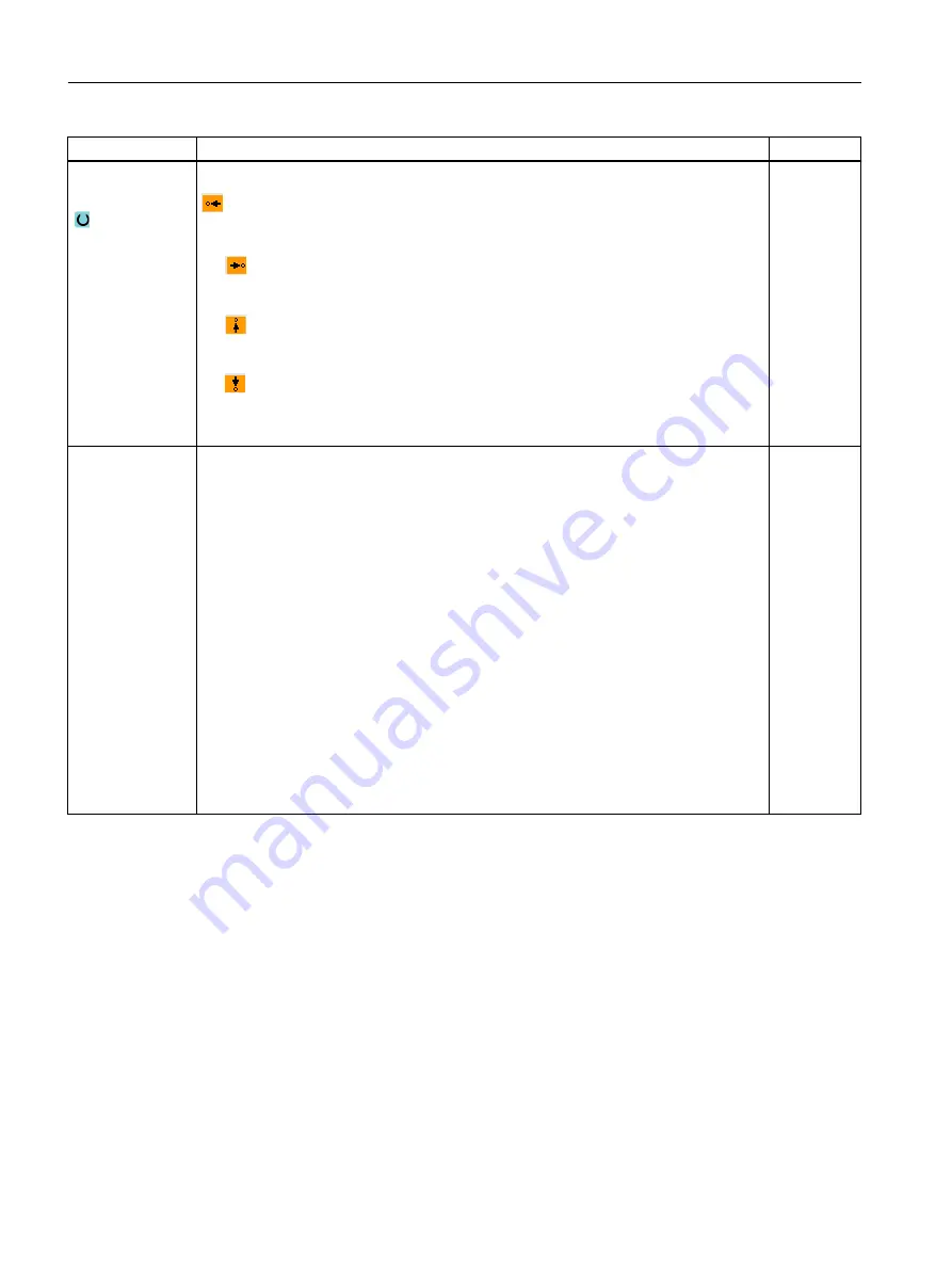
Direction in front
of the contour
Direction of the contour element towards the starting point:
● In the negative direction of the horizontal axis
● In the positive direction of the horizontal axis
● In the negative direction of the vertical axis
● In the positive direction of the vertical axis
Additional com‐
mands
You can enter additional commands in the form of G code for each contour element. You
can enter the additional commands (max. 40 characters) in the extended parameter
screens ("All parameters" softkey). The softkey is always available at the starting point, it
only has to be pressed when entering additional contour elements.
You can program feedrates and M commands, for example, using additional G code
commands. However, carefully ensure that the additional commands do not collide with
the generated G code of the contour and are compatible with the machining type required.
Therefore, do not use any G code commands of group 1 (G0, G1, G2, G3), no coordinates
in the plane and no G code commands that have to be programmed in a separate block.
The contour is finished in continuous-path mode (G64). As a result, contour transitions
such as corners, chamfers or radii may not be machined precisely.
If you wish to avoid this, then it is possible to use additional commands when programming.
Example:
For a contour, first program the straight X parallel and then enter "G9" (non-modal exact
stop) for the additional command parameter. Then program the Z-parallel straight line.
The corner will be machined exactly, as the feedrate at the end of the X-parallel straight
line is briefly zero.
Note:
The additional commands are only effective for finishing!
10.3.4
Creating contour elements
Creating contour elements
After you have created a new contour and specified the starting point, you can define the
individual elements that make up the contour.
The following contour elements are available for the definition of a contour:
● Straight vertical line
● Straight horizontal line
Programming technology functions (cycles)
10.3 Contour turning
Turning
446
Operating Manual, 06/2019, A5E44903486B AB
Содержание SINUMERIK 840D sl
Страница 8: ...Preface Turning 8 Operating Manual 06 2019 A5E44903486B AB ...
Страница 70: ...Introduction 2 4 User interface Turning 70 Operating Manual 06 2019 A5E44903486B AB ...
Страница 274: ... Creating a G code program 8 8 Selection of the cycles via softkey Turning 274 Operating Manual 06 2019 A5E44903486B AB ...
Страница 275: ... Creating a G code program 8 8 Selection of the cycles via softkey Turning Operating Manual 06 2019 A5E44903486B AB 275 ...
Страница 282: ...Creating a G code program 8 10 Measuring cycle support Turning 282 Operating Manual 06 2019 A5E44903486B AB ...
Страница 344: ...Creating a ShopTurn program 9 19 Example Standard machining Turning 344 Operating Manual 06 2019 A5E44903486B AB ...
Страница 716: ...Collision avoidance 12 2 Set collision avoidance Turning 716 Operating Manual 06 2019 A5E44903486B AB ...
Страница 774: ...Tool management 13 15 Working with multitool Turning 774 Operating Manual 06 2019 A5E44903486B AB ...
Страница 834: ...Managing programs 14 19 RS 232 C Turning 834 Operating Manual 06 2019 A5E44903486B AB ...
Страница 856: ...Alarm error and system messages 15 9 Remote diagnostics Turning 856 Operating Manual 06 2019 A5E44903486B AB ...
Страница 892: ...Working with two tool carriers 18 2 Measure tool Turning 892 Operating Manual 06 2019 A5E44903486B AB ...
Страница 912: ...HT 8 840D sl only 20 5 Calibrating the touch panel Turning 912 Operating Manual 06 2019 A5E44903486B AB ...
Страница 927: ...Appendix A A 1 840D sl 828D documentation overview Turning Operating Manual 06 2019 A5E44903486B AB 927 ...


