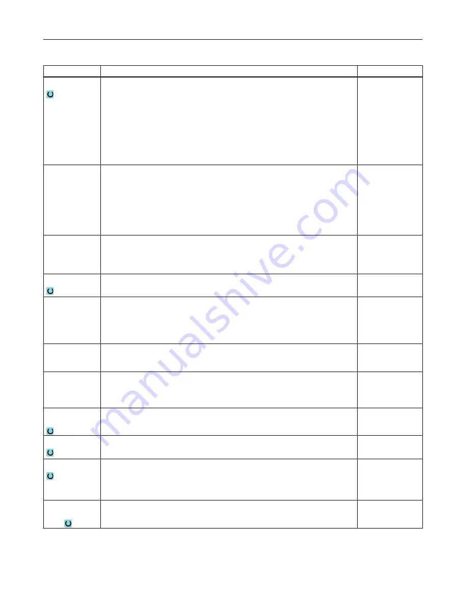
Parameter
Description
Unit
DF
Infeed:
● Degression amount by which each additional infeed is reduced.
● Percentage for each additional infeed.
DF = 100%: Infeed increment remains constant.
DF < 100%: Infeed increment is reduced in direction of final drilling depth.
Example: Last infeed was 4 mm; DF is 80%
Next infeed = 4 x 80% = 3.2 mm
Next infeed = 3.2 x 80% = 2.56 mm, etc.
mm
%
V1
Minimum infeed - (only for DF in %)
Parameter V1 is only available if DF<100 has been programmed.
If the infeed increment becomes very small, a minimum infeed can be programmed
in parameter "V1".
V1 < Infeed increment: The tool is inserted by the infeed increment.
V1 > Infeed increment: The tool is inserted by the infeed value programmed under
V1.
mm
V2
(only for chip
breaking and
soft first cut "no")
Retraction distance after each machining step.
Distance by which the drill is retracted for chip breaking.
V2 = 0: The tool is not retracted but is left in place for one revolution.
mm
DTB
● Dwell time at drilling depth in seconds
● Dwell time at drilling depth in revolutions
s
rev
Clearance dis‐
tance
(only for swarf re‐
moval and soft
first cut "no")
● Manual
The clearance distance must be entered manually.
● Automatic
The clearance distance is calculated by the cycle.
V3 – (for "man‐
ual" clearance
distance only)
Clearance distance (inc)
mm
N - (only for
"chip breaking
and swarf re‐
moval")
Number of chip breaking strokes before each swarf removal operation.
Retraction for
swarf removal
● Swarf removal at the pilot hole depth
● Swarf removal at the safety clearance
DTS
● Dwell time for swarf removal in seconds
● Dwell time for swarf removal in revolutions
s
rev
Through drilling
● Yes
Through drilling with feedrate FD
● No
Drilling with constant feedrate
ZD - (only for
through drilling
"yes")
Depth for through drilling feedrate (abs) or depth for through drilling feedrate in
relation to Z1 (inc)
mm
Programming technology functions (cycles)
10.1 Drilling
Turning
Operating Manual, 06/2019, A5E44903486B AB
369
Содержание SINUMERIK 840D sl
Страница 8: ...Preface Turning 8 Operating Manual 06 2019 A5E44903486B AB ...
Страница 70: ...Introduction 2 4 User interface Turning 70 Operating Manual 06 2019 A5E44903486B AB ...
Страница 274: ... Creating a G code program 8 8 Selection of the cycles via softkey Turning 274 Operating Manual 06 2019 A5E44903486B AB ...
Страница 275: ... Creating a G code program 8 8 Selection of the cycles via softkey Turning Operating Manual 06 2019 A5E44903486B AB 275 ...
Страница 282: ...Creating a G code program 8 10 Measuring cycle support Turning 282 Operating Manual 06 2019 A5E44903486B AB ...
Страница 344: ...Creating a ShopTurn program 9 19 Example Standard machining Turning 344 Operating Manual 06 2019 A5E44903486B AB ...
Страница 716: ...Collision avoidance 12 2 Set collision avoidance Turning 716 Operating Manual 06 2019 A5E44903486B AB ...
Страница 774: ...Tool management 13 15 Working with multitool Turning 774 Operating Manual 06 2019 A5E44903486B AB ...
Страница 834: ...Managing programs 14 19 RS 232 C Turning 834 Operating Manual 06 2019 A5E44903486B AB ...
Страница 856: ...Alarm error and system messages 15 9 Remote diagnostics Turning 856 Operating Manual 06 2019 A5E44903486B AB ...
Страница 892: ...Working with two tool carriers 18 2 Measure tool Turning 892 Operating Manual 06 2019 A5E44903486B AB ...
Страница 912: ...HT 8 840D sl only 20 5 Calibrating the touch panel Turning 912 Operating Manual 06 2019 A5E44903486B AB ...
Страница 927: ...Appendix A A 1 840D sl 828D documentation overview Turning Operating Manual 06 2019 A5E44903486B AB 927 ...


