


Taking into account the tailstock
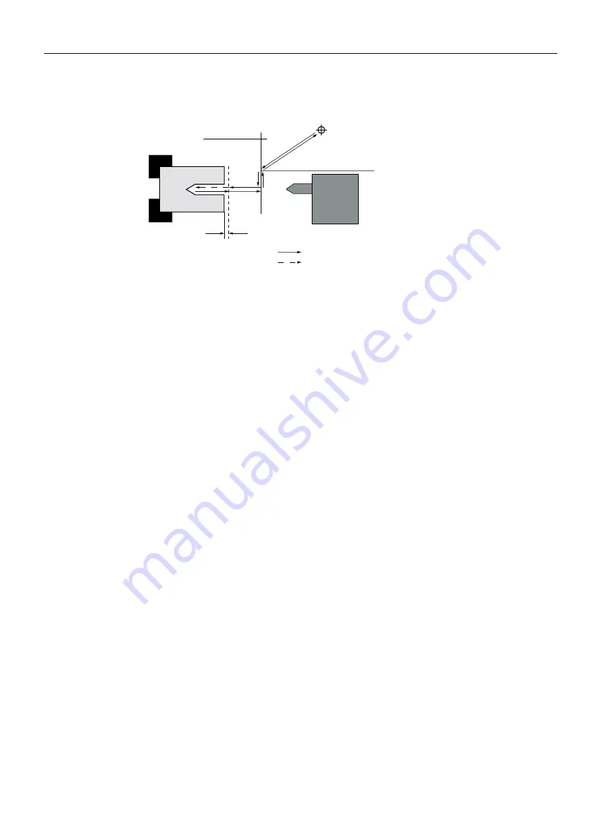
0DFKLQLQJIHHGUDWH
5DSLGWUDYHUVH
7RROFKDQJHSRLQW
5HWUDFWLRQSODQH
6DIHW\FOHDUDQFH
;55
Figure 9-6
Approach/retraction taking into account the tailstock
● The tool traverses in rapid traverse from the tool change point along the shortest path to the
retraction plane XRR from the tailstock.
● After this, the tool traverses in rapid traverse on the retraction plane in the X direction.
● After this, the tool traverses in rapid traverse to the safety clearance.
● Following this, the workpiece is then machined with the programmed machining feedrate.
● After machining, the tool retracts with rapid traverse to the safety clearance.
● The tool then continues to traverse vertically in rapid traverse to the retraction plane.
● After this, the tool traverses in the X direction to the retraction plane XRR from the tailstock.
● From there, the tool traverses in rapid traverse along the shortest path to the tool change
point. If the tool does not need to be changed between two machining processes, the tool
traverses from the retraction plane to the next machining cycle.
You define the tool change point, the retraction plane, the safety clearance, and the retraction
plane for the tailstock in the program header.
See also
Programming the approach/retraction cycle (Page 322)
Program header (Page 300)
9.4.3
Absolute and incremental dimensions
When generating a machining step program, you can input positions in absolute or incremental
dimensions, depending on how the workpiece drawing is dimensioned.
You can also use a combination of absolute and incremental dimensions, i.e. one coordinate
as an absolute dimension and the other as an incremental dimension.
For the face axis (the X axis, in this case), in the machine data it is established whether the
diameter or radius is programmed in absolute or incremental dimensions.
Please refer to the machine manufacturer's specifications.
Creating a ShopTurn program
9.4 Fundamentals
Turning
294
Operating Manual, 06/2019, A5E44903486B AB
Содержание SINUMERIK 840D sl
Страница 8: ...Preface Turning 8 Operating Manual 06 2019 A5E44903486B AB ...
Страница 70: ...Introduction 2 4 User interface Turning 70 Operating Manual 06 2019 A5E44903486B AB ...
Страница 274: ... Creating a G code program 8 8 Selection of the cycles via softkey Turning 274 Operating Manual 06 2019 A5E44903486B AB ...
Страница 275: ... Creating a G code program 8 8 Selection of the cycles via softkey Turning Operating Manual 06 2019 A5E44903486B AB 275 ...
Страница 282: ...Creating a G code program 8 10 Measuring cycle support Turning 282 Operating Manual 06 2019 A5E44903486B AB ...
Страница 344: ...Creating a ShopTurn program 9 19 Example Standard machining Turning 344 Operating Manual 06 2019 A5E44903486B AB ...
Страница 716: ...Collision avoidance 12 2 Set collision avoidance Turning 716 Operating Manual 06 2019 A5E44903486B AB ...
Страница 774: ...Tool management 13 15 Working with multitool Turning 774 Operating Manual 06 2019 A5E44903486B AB ...
Страница 834: ...Managing programs 14 19 RS 232 C Turning 834 Operating Manual 06 2019 A5E44903486B AB ...
Страница 856: ...Alarm error and system messages 15 9 Remote diagnostics Turning 856 Operating Manual 06 2019 A5E44903486B AB ...
Страница 892: ...Working with two tool carriers 18 2 Measure tool Turning 892 Operating Manual 06 2019 A5E44903486B AB ...
Страница 912: ...HT 8 840D sl only 20 5 Calibrating the touch panel Turning 912 Operating Manual 06 2019 A5E44903486B AB ...
Страница 927: ...Appendix A A 1 840D sl 828D documentation overview Turning Operating Manual 06 2019 A5E44903486B AB 927 ...


