


Commissioning
5.6 Commissioning in speed control mode (S)
SINAMICS V90, SIMOTICS S-1FL6
184
Operating Instructions, 04/2019, A5E36037884-007
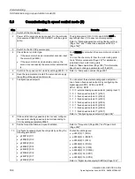
5.6
Commissioning in speed control mode (S)
Step
Description
Remarks
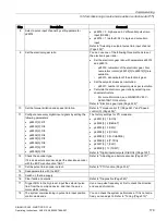
1
Switch off the line supply.
2
Power off the servo drive and connect it to the controller
(for example, SIMATIC S7-200 SMART) with the signal
cable.
The digital signals CWL, CCWL and EMGS must be
kept at high level (1) to ensure normal operation.
Refer to "Standard application wiring (factory setting)
(Page 136)" and "Connection examples with PLCs
(Page 146)".
3
Switch on the 24 VDC power supply.
4
Check the servo motor type.
•
If the servo motor has an incremental encoder, input
the motor ID (p29000).
•
If the servo motor has an absolute encoder, the
servo drive can identify the servo motor automatical-
ly.
Fault F52984 occurs when the servo motor is not identi-
fied.
You can find the motor ID from the motor rating plate.
Go to "Motor components (Page 30)" for detailed de-
scriptions about motor rating plate.
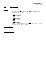
Refer to "Basic operations (Page 195)" for information
about how to change a parameter with the BOP.
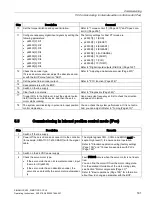
5
Switch to the speed control mode by setting p29003 = 2. Refer to "Compound controls (Page 209)".
6
Save the parameter and restart the servo drive to apply
the setting of the speed control mode.
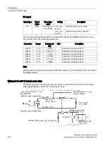
7
Configure speed setpoint.
You can select the external analog speed setpoint or
one of seven fixed speed setpoints by configuring the
digital signals SPD3, SPD2 and SPD1.
SPD3 : SPD2 : SPD1
0 : 0 : 0: external analog speed setpoint (analog input 1)
0 : 0 : 1: fixed speed setpoint 1 (p1001)
0 : 1 : 0: fixed speed setpoint 2 (p1002)
0 : 1 : 1: fixed speed setpoint 3 (p1003)
1 : 0 : 0: fixed speed setpoint 4 (p1004)
1 : 0 : 1: fixed speed setpoint 5 (p1005)
1 : 1 : 0: fixed speed setpoint 6 (p1006)
1 : 1 : 1: fixed speed setpoint 7 (p1007)
Refer to "Configuring speed setpoint (Page 256)".
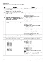
8
If the external analog speed setpoint is used, configure
the maximum analog speed setpoint corresponding to
10 V by setting parameter p29060.
9
Set the torque limitation and speed limitation.
Refer to "Torque limit (Page 259)" and "Speed limit
(Page 259)".
10 Configure necessary digital input signals by setting the
following parameters:
•
p29301[2]: DI1
•
p29302[2]: DI2
•
p29303[2]: DI3
•
p29304[2]: DI4
•
p29305[2]:
DI5
•
p29306[2]: DI6
•
p29307[2]: DI7
•
p29308[2]: DI8
The factory settings are:
•
p29301[2]: 1 (SON)
•
p29302[2]: 2 (RESET)
•
p29303[2]: 3 (CWL)
•
p29304[2]: 4 (CCWL)
•
p29305[2]: 12 (CWE)
•
p29306[2]: 13 (CCWE)
•
p29307[2]: 15 (SPD1)
•
p29308[2]: 16 (SPD2)
Refer to "Digital inputs/outputs (DIs/DOs) (Page 122)".
Содержание SIMOTICS S-1FL6
Страница 1: ...SINAMICS V90 SIMOTICS S 1FL6 ...
Страница 2: ......
Страница 87: ...Mounting 3 1 Mounting the drive SINAMICS V90 SIMOTICS S 1FL6 Operating Instructions 04 2019 A5E36037884 007 85 ...
Страница 89: ...Mounting 3 1 Mounting the drive SINAMICS V90 SIMOTICS S 1FL6 Operating Instructions 04 2019 A5E36037884 007 87 ...
Страница 342: ...Tuning 9 9 PI P switching SINAMICS V90 SIMOTICS S 1FL6 340 Operating Instructions 04 2019 A5E36037884 007 ...
Страница 384: ...Parameters 10 2 Parameter list SINAMICS V90 SIMOTICS S 1FL6 382 Operating Instructions 04 2019 A5E36037884 007 ...
Страница 432: ......


