


Connecting
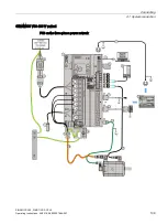
4.2 Main circuit wiring
SINAMICS V90, SIMOTICS S-1FL6
116
Operating Instructions, 04/2019, A5E36037884-007
4.2.2
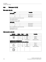
Motor power - U, V, W
Motor output - drive side
Signal
Description
200 V variant
U
Motor phase U
V
Motor phase V
W
Motor phase W
Recommended minimum cable cross-section:
FSA and FSB: 0.75 mm
2
FSC and FSD (1 kW): 0.75 mm
2
FSD (1.5 kW to 2 kW): 2.5 mm
2
400 V variant
U
Motor phase U
V
Motor phase V
W
Motor phase W
Recommended minimum cable cross-section:
FSAA and FSA: 1.5 mm
2
FSB and FSC: 2.5 mm
2
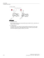
Power connector - motor side
Illustration
Pin No.
Signal
Color
Description
Low inertia motor, shaft-height: 20 mm, 30 mm, and 40 mm
1
U
Black
Phase U
2
V
Black
Phase V
3
W
Black
Phase W
4
PE
Yellow-green
Protective earthing
Low inertia motor, shaft-height: 50 mm
High inertia motor, shaft-height: 45 mm, 60 mm, and 90 mm
Straight connectors:
Angular connectors:
1
U
Black
Phase U
2
V
Black
Phase V
3
W
Black
Phase W
4/
PE
Yellow-green
Protective earthing
Содержание SIMOTICS S-1FL6
Страница 1: ...SINAMICS V90 SIMOTICS S 1FL6 ...
Страница 2: ......
Страница 87: ...Mounting 3 1 Mounting the drive SINAMICS V90 SIMOTICS S 1FL6 Operating Instructions 04 2019 A5E36037884 007 85 ...
Страница 89: ...Mounting 3 1 Mounting the drive SINAMICS V90 SIMOTICS S 1FL6 Operating Instructions 04 2019 A5E36037884 007 87 ...
Страница 342: ...Tuning 9 9 PI P switching SINAMICS V90 SIMOTICS S 1FL6 340 Operating Instructions 04 2019 A5E36037884 007 ...
Страница 384: ...Parameters 10 2 Parameter list SINAMICS V90 SIMOTICS S 1FL6 382 Operating Instructions 04 2019 A5E36037884 007 ...
Страница 432: ......


