


Connecting
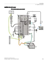
4.2 Main circuit wiring
SINAMICS V90, SIMOTICS S-1FL6
114
Operating Instructions, 04/2019, A5E36037884-007
4.2
Main circuit wiring
4.2.1
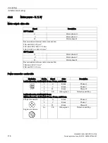
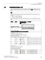
Line supply - L1, L2, L3
Signal
Description
200 V variant
L1
Line phase L1
L2
Line phase L2
L3
Line phase L3
Recommended minimum cable cross-section:
When used on the single phase power network:
FSA: 0.75 mm
2
FSB: 0.52 mm
2
FSC: 1.31 mm
2
When used on the three phase power network:
FSA: 0.75 mm
2
FSB: 0.33 mm
2
FSC: 0.52 mm
2
FSD (1 kW): 0.82 mm
2
FSD (1.5 kW to 2 kW): 2.08 mm
2
400 V variant
L1
Line phase L1
L2
Line phase L2
L3
Line phase L3
Recommended minimum cable cross-section:
FSAA and FSA: 1.5 mm
2
FSB and FSC: 2.5 mm
2
Note
For 200 V variant servo drive, when using the FSA, FSB and FSC on the single phase power
network, you can connect the power supply to any two connectors of L1, L2, and L3.
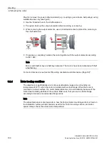
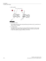
Assembling the line supply cable terminals
The procedure of assembling a line supply cable terminal is the same as that for a power
cable terminal on the drive side.
For more information, see Section "Assembly of cable terminals/connectors on the drive side
(Page 411)".
Содержание SIMOTICS S-1FL6
Страница 1: ...SINAMICS V90 SIMOTICS S 1FL6 ...
Страница 2: ......
Страница 87: ...Mounting 3 1 Mounting the drive SINAMICS V90 SIMOTICS S 1FL6 Operating Instructions 04 2019 A5E36037884 007 85 ...
Страница 89: ...Mounting 3 1 Mounting the drive SINAMICS V90 SIMOTICS S 1FL6 Operating Instructions 04 2019 A5E36037884 007 87 ...
Страница 342: ...Tuning 9 9 PI P switching SINAMICS V90 SIMOTICS S 1FL6 340 Operating Instructions 04 2019 A5E36037884 007 ...
Страница 384: ...Parameters 10 2 Parameter list SINAMICS V90 SIMOTICS S 1FL6 382 Operating Instructions 04 2019 A5E36037884 007 ...
Страница 432: ......


