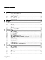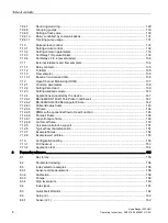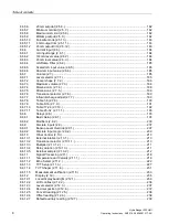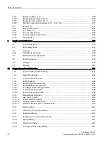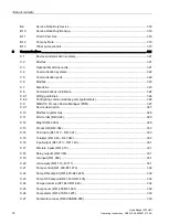
Table of contents
HydroRanger 200 HMI
Operating Instructions, 06/2018, A5E36281317-AC
5
7.3.8
Relay activation ....................................................................................................................... 99
7.3.9
Preset applications ................................................................................................................ 100
7.3.10
Relay fail-safe ....................................................................................................................... 104
7.3.11
Security ................................................................................................................................. 104
7.3.12
Parameter types .................................................................................................................... 104
7.3.13
Display readout ..................................................................................................................... 104
7.3.14
Adjusting the primary reading ............................................................................................... 105
7.4
Backup level override............................................................................................................ 105
7.4.1
Backup level override parameters ........................................................................................ 106
7.5
Discrete inputs ...................................................................................................................... 106
7.5.1
Wiring the discrete inputs ..................................................................................................... 107
7.5.2
Adjusting the discrete input logic .......................................................................................... 107
7.6
mA I/0 .................................................................................................................................... 107
7.6.1
mA Input ................................................................................................................................ 107
7.6.2
mA Output ............................................................................................................................. 108
7.7
Volume .................................................................................................................................. 109
7.7.1
Readings ............................................................................................................................... 109
7.7.2
Vessel shape and dimensions .............................................................................................. 110
7.7.3
Characterization chart ........................................................................................................... 111
7.8
Alarms ................................................................................................................................... 113
7.8.1
Level ..................................................................................................................................... 113
7.8.2
Setting simple level alarms ................................................................................................... 114
7.8.3
Rate ...................................................................................................................................... 114
7.8.4
In-bounds/Out-of-bounds Range .......................................................................................... 115
7.8.5
Cable fault ............................................................................................................................. 115
7.8.6
Temperature ......................................................................................................................... 116
7.8.7
Loss of Echo (LOE) ............................................................................................................... 116
7.9
Pump control ......................................................................................................................... 117
7.9.1
Setting a pump down group .................................................................................................. 117
7.9.1.1
Set relays to Alternate Duty Assist ....................................................................................... 118
7.9.1.2
Set the ON setpoints ............................................................................................................. 118
7.9.1.3
Set the OFF setpoints ........................................................................................................... 118
7.9.2
Setting a pump up (reservoir) group ..................................................................................... 119
7.9.2.1
Set relays to Alternate Duty Assist ....................................................................................... 120
7.9.2.2
Set the Relay ON Setpoints .................................................................................................. 120
7.9.2.3
Set the Relay OFF Setpoints ................................................................................................ 120
7.9.3
Other pump control algorithms ............................................................................................. 121
7.9.3.1
Set relays to Alternate Duty Backup ..................................................................................... 121
7.9.3.2
Set relays to Fixed Duty Assist ............................................................................................. 121
7.9.3.3
Set relays to Fixed Duty Backup ........................................................................................... 122
7.9.3.4
Set relays to Service Ratio Duty Assist ................................................................................ 123
7.9.3.5
Set relays to First in First Out ............................................................................................... 124
7.9.4
Optional pump controls ......................................................................................................... 125
7.9.4.1
Starting pumps by rate of level change ................................................................................ 125
7.9.4.2
Rotating pumps by service ratio ........................................................................................... 126
7.9.4.3
Totalizing pumped volume .................................................................................................... 127
7.9.4.4
Setting independent fail-safe controls................................................................................... 128
7.9.4.5
Setting a pump to Run-ON ................................................................................................... 128
7.9.4.6
Setting the pump start delays ............................................................................................... 129
Содержание HydroRanger 200 HMI
Страница 2: ......
Страница 20: ...Introduction 1 5 Notes on warranty HydroRanger 200 HMI 18 Operating Instructions 06 2018 A5E36281317 AC ...
Страница 24: ...Safety notes HydroRanger 200 HMI 22 Operating Instructions 06 2018 A5E36281317 AC ...
Страница 28: ...Description 3 5 Modbus communication HydroRanger 200 HMI 26 Operating Instructions 06 2018 A5E36281317 AC ...
Страница 159: ...Parameter reference 8 2 Parameter indexing HydroRanger 200 HMI Operating Instructions 06 2018 A5E36281317 AC 157 ...
Страница 276: ...Parameter reference 8 10 Language 6 HydroRanger 200 HMI 274 Operating Instructions 06 2018 A5E36281317 AC ...
Страница 322: ...Pump control reference B 13 Other pump controls HydroRanger 200 HMI 320 Operating Instructions 06 2018 A5E36281317 AC ...
Страница 352: ...Communications C 41 Single parameter access SPA HydroRanger 200 HMI 350 Operating Instructions 06 2018 A5E36281317 AC ...
Страница 354: ...Updating software HydroRanger 200 HMI 352 Operating Instructions 06 2018 A5E36281317 AC ...
Страница 359: ...HydroRanger 200 HMI Operating Instructions 06 2018 A5E36281317 AC 357 Conduit entry for Class I Div 2 applications F ...
Страница 360: ...Conduit entry for Class I Div 2 applications HydroRanger 200 HMI 358 Operating Instructions 06 2018 A5E36281317 AC ...
Страница 361: ...Conduit entry for Class I Div 2 applications HydroRanger 200 HMI Operating Instructions 06 2018 A5E36281317 AC 359 ...
Страница 362: ......
Страница 372: ...Programming chart G 1 Programming chart HydroRanger 200 HMI 370 Operating Instructions 06 2018 A5E36281317 AC ...
Страница 390: ...LCD menu structure H 1 LCD Menu Structure HydroRanger 200 HMI 388 Operating Instructions 06 2018 A5E36281317 AC ...
Страница 403: ......


