Commissioning
6.5 Quick Start Wizards
HydroRanger 200 HMI
60
Operating Instructions, 06/2018, A5E36281317-AC
6.5.1
Setting wizards via graphical display
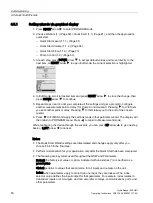
1.
Press RIGHT arrow to enter PROGRAM mode.
2.
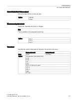
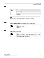
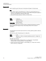
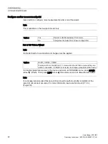
Choose Wizards (1.) (Page 59) > Quick Start (1.1) (Page 61), and then the appropriate
quick start:
–
Quick Start Level (1.1.1.) (Page 61)
–
Quick Start Volume (1.1.2.) (Page 66)
–
Quick Start Flow (1.1.3.) (Page 73)
–
Pump Control (1.2.) (Page 83)
3.
At each step, press DOWN arrow to accept default values and move directly to the
next item, or RIGHT arrow to open Edit mode: the current selection is highlighted.
4.
In Edit mode, scroll to desired item and press RIGHT arrow to store the change, then
press DOWN arrow to continue.
5.
Repeat steps 3 and 4 until you complete all the settings and get a prompt to configure
another measurement point or relay (for Pump Control wizard). Pressing for YES lets
you set another point or relay. Pressing for NO takes you to the end of the chosen
wizard.
6.
Press to FINISH and apply the settings made in that particular wizard. The display will
then return to PROGRAM menu. Press to return to Measurement mode.
While configuring the device through the wizards, you can press UP arrow to go one step
back, or LEFT arrow to cancel.
Notes:
●
The Quick Start Wizard settings are inter-related and changes apply only after you
choose Finish in the final step.
●
Perform customization for your application only after the Quick Start has been completed.
●
The following are key terms used throughout the QSW and Parameters:
Default: the factory-set value or option; indicated with an asterisk (*) or specified as a
preset value.
Global: pertains to values that are common for all inputs and outputs on the unit.
Index: when parameters apply to more than one input, they are indexed. The index
selector value defines the input/output for that parameter. For example, index relates to
transducer inputs or mA outputs, and can also refer to relays, communications ports, and
other parameters.
Содержание HydroRanger 200 HMI
Страница 2: ......
Страница 20: ...Introduction 1 5 Notes on warranty HydroRanger 200 HMI 18 Operating Instructions 06 2018 A5E36281317 AC ...
Страница 24: ...Safety notes HydroRanger 200 HMI 22 Operating Instructions 06 2018 A5E36281317 AC ...
Страница 28: ...Description 3 5 Modbus communication HydroRanger 200 HMI 26 Operating Instructions 06 2018 A5E36281317 AC ...
Страница 159: ...Parameter reference 8 2 Parameter indexing HydroRanger 200 HMI Operating Instructions 06 2018 A5E36281317 AC 157 ...
Страница 276: ...Parameter reference 8 10 Language 6 HydroRanger 200 HMI 274 Operating Instructions 06 2018 A5E36281317 AC ...
Страница 322: ...Pump control reference B 13 Other pump controls HydroRanger 200 HMI 320 Operating Instructions 06 2018 A5E36281317 AC ...
Страница 352: ...Communications C 41 Single parameter access SPA HydroRanger 200 HMI 350 Operating Instructions 06 2018 A5E36281317 AC ...
Страница 354: ...Updating software HydroRanger 200 HMI 352 Operating Instructions 06 2018 A5E36281317 AC ...
Страница 359: ...HydroRanger 200 HMI Operating Instructions 06 2018 A5E36281317 AC 357 Conduit entry for Class I Div 2 applications F ...
Страница 360: ...Conduit entry for Class I Div 2 applications HydroRanger 200 HMI 358 Operating Instructions 06 2018 A5E36281317 AC ...
Страница 361: ...Conduit entry for Class I Div 2 applications HydroRanger 200 HMI Operating Instructions 06 2018 A5E36281317 AC 359 ...
Страница 362: ......
Страница 372: ...Programming chart G 1 Programming chart HydroRanger 200 HMI 370 Operating Instructions 06 2018 A5E36281317 AC ...
Страница 390: ...LCD menu structure H 1 LCD Menu Structure HydroRanger 200 HMI 388 Operating Instructions 06 2018 A5E36281317 AC ...
Страница 403: ......

