Installing/mounting
4.1 Basic safety notes
HydroRanger 200 HMI
28
Operating Instructions, 06/2018, A5E36281317-AC
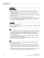
WARNING
Improper installation
Danger to personnel, system and environment can result from improper installation.
•
Installation shall only be performed by qualified personnel and in accordance with local
governing regulations.
•
This product is susceptible to electrostatic shock. Follow proper grounding procedures.
•
All field wiring shall have insulation suitable for the highest applied input or relay voltage
(whichever is greater).
•
Hazardous voltages present on transducer terminals during operation.
•
DC input terminals shall be supplied from a source providing electrical isolation between
the input and output, in order to meet applicable safety requirements of IEC 61010-1
(e.g. Class 2 or Limited Energy Source).
CAUTION
Electrostatic discharge precaution
Observe electrostatic discharge precautions prior to handling electronic components within
the wiring compartment.
Note
•
If relay contact terminals are used to control hazardous live circuits (
≥ 16
Vrms @ 0.5 A),
the equipment connected to the relay contacts shall have no accessible live parts and its
wiring shall have insulation suitable for the highest applied input or relay voltage
(whichever is greater). The maximum allowable working voltage between adjacent relay
contacts shall be 250 V.
•
The non-metallic enclosure does not provide grounding between conduit connections.
Use grounding type bushings and jumpers.
•
Before opening the lid, ensure that the inside of the enclosure will not be contaminated
with liquids or dust from the local environment.
Note
•
Ensure power is removed from the device before servicing. Follow all local electrical
safety codes and guidelines.
•
Ensure power is removed from the device before disconnecting or connecting the HMI.
•
If the device is to be shipped by air for any reason, e.g. return to the factory for repair,
etc., use the pressure relief tag, or similar means, installed between the lid and enclosure
base.
•
[AC-Powered Units] All current-carrying conductors must be protected by a fuse or circuit
breaker in the building installation, having a breaking capacity of up to 15 A.
Содержание HydroRanger 200 HMI
Страница 2: ......
Страница 20: ...Introduction 1 5 Notes on warranty HydroRanger 200 HMI 18 Operating Instructions 06 2018 A5E36281317 AC ...
Страница 24: ...Safety notes HydroRanger 200 HMI 22 Operating Instructions 06 2018 A5E36281317 AC ...
Страница 28: ...Description 3 5 Modbus communication HydroRanger 200 HMI 26 Operating Instructions 06 2018 A5E36281317 AC ...
Страница 159: ...Parameter reference 8 2 Parameter indexing HydroRanger 200 HMI Operating Instructions 06 2018 A5E36281317 AC 157 ...
Страница 276: ...Parameter reference 8 10 Language 6 HydroRanger 200 HMI 274 Operating Instructions 06 2018 A5E36281317 AC ...
Страница 322: ...Pump control reference B 13 Other pump controls HydroRanger 200 HMI 320 Operating Instructions 06 2018 A5E36281317 AC ...
Страница 352: ...Communications C 41 Single parameter access SPA HydroRanger 200 HMI 350 Operating Instructions 06 2018 A5E36281317 AC ...
Страница 354: ...Updating software HydroRanger 200 HMI 352 Operating Instructions 06 2018 A5E36281317 AC ...
Страница 359: ...HydroRanger 200 HMI Operating Instructions 06 2018 A5E36281317 AC 357 Conduit entry for Class I Div 2 applications F ...
Страница 360: ...Conduit entry for Class I Div 2 applications HydroRanger 200 HMI 358 Operating Instructions 06 2018 A5E36281317 AC ...
Страница 361: ...Conduit entry for Class I Div 2 applications HydroRanger 200 HMI Operating Instructions 06 2018 A5E36281317 AC 359 ...
Страница 362: ......
Страница 372: ...Programming chart G 1 Programming chart HydroRanger 200 HMI 370 Operating Instructions 06 2018 A5E36281317 AC ...
Страница 390: ...LCD menu structure H 1 LCD Menu Structure HydroRanger 200 HMI 388 Operating Instructions 06 2018 A5E36281317 AC ...
Страница 403: ......


