Operating
7.11 External totalizers and flow samplers
HydroRanger 200 HMI
Operating Instructions, 06/2018, A5E36281317-AC
135
7.11.1
Relay contacts
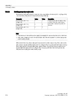
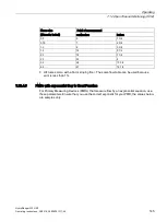
Pumped volume is calculated at the end of the pump cycle. Totalized volume given through
a relay set up for totalizer [Relay Function (2.8.1.4.) (Page 195) = Totalizer] will be given in
bursts at this time.
Both the open and closed times for the relay contact are provided by Relay Duration
(2.10.1.3.) (Page 211) and are preset to 0.2 seconds. Partial units are added to the next
pump cycle.
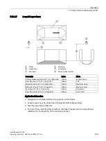
Example:
A relay set up to make one contact for every cubic meter (m
3
) of liquid.
①
Relay Duration (2.10.1.3.) (Page 211)
②
Pump cycle
7.11.2
Totalizer
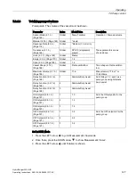
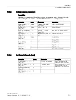
To set the totalizer to provide relay contact to an external counter, use the following:
Counter formula
1 Contact per 10
Multiplier (2.10.1.2.)
units
Multiplier (2.10.1.2.) (Page 211) is preset to 0 so the default
number of contacts for a pumped volume cycle is equivalent
to the number of volume units.
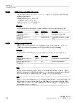
The source of units depends on the operation:
Operation
Units source parameter
OCM [Sensor Mode (2.1.3.) (Page 163) = Flow
rate in open channel]
Maximum Flow (2.13.4.3.) (Page 243) or Flowrate
Units (2.13.4.7.) (Page 245)
Pumped Volume [Sensor Mode (2.1.3.)
(Page 163) = Pump Totalizer]
Maximum Volume (2.7.3.) (Page 188)
Содержание HydroRanger 200 HMI
Страница 2: ......
Страница 20: ...Introduction 1 5 Notes on warranty HydroRanger 200 HMI 18 Operating Instructions 06 2018 A5E36281317 AC ...
Страница 24: ...Safety notes HydroRanger 200 HMI 22 Operating Instructions 06 2018 A5E36281317 AC ...
Страница 28: ...Description 3 5 Modbus communication HydroRanger 200 HMI 26 Operating Instructions 06 2018 A5E36281317 AC ...
Страница 159: ...Parameter reference 8 2 Parameter indexing HydroRanger 200 HMI Operating Instructions 06 2018 A5E36281317 AC 157 ...
Страница 276: ...Parameter reference 8 10 Language 6 HydroRanger 200 HMI 274 Operating Instructions 06 2018 A5E36281317 AC ...
Страница 322: ...Pump control reference B 13 Other pump controls HydroRanger 200 HMI 320 Operating Instructions 06 2018 A5E36281317 AC ...
Страница 352: ...Communications C 41 Single parameter access SPA HydroRanger 200 HMI 350 Operating Instructions 06 2018 A5E36281317 AC ...
Страница 354: ...Updating software HydroRanger 200 HMI 352 Operating Instructions 06 2018 A5E36281317 AC ...
Страница 359: ...HydroRanger 200 HMI Operating Instructions 06 2018 A5E36281317 AC 357 Conduit entry for Class I Div 2 applications F ...
Страница 360: ...Conduit entry for Class I Div 2 applications HydroRanger 200 HMI 358 Operating Instructions 06 2018 A5E36281317 AC ...
Страница 361: ...Conduit entry for Class I Div 2 applications HydroRanger 200 HMI Operating Instructions 06 2018 A5E36281317 AC 359 ...
Страница 362: ......
Страница 372: ...Programming chart G 1 Programming chart HydroRanger 200 HMI 370 Operating Instructions 06 2018 A5E36281317 AC ...
Страница 390: ...LCD menu structure H 1 LCD Menu Structure HydroRanger 200 HMI 388 Operating Instructions 06 2018 A5E36281317 AC ...
Страница 403: ......

