Parameter reference
8.6 Setup (2.)
HydroRanger 200 HMI
Operating Instructions, 06/2018, A5E36281317-AC
243
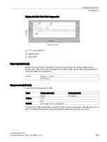
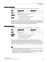
Maximum head (2.13.4.2.)
Sets the level value associated with Maximum Flow, in Units (2.1.1.) (Page 162).
Index
Single-point model
Dual-point model
Global
Transducer
Values
Range: -999 ... 9999
Preset: Span (2.2.2.) (Page 169) value
Altered by
•
Units (2.1.1.) (Page 162)
•
Primary measuring device (2.13.2.) (Page 240)
Related
•
Maximum flow (2.13.4.3.) (Page 243)
•
Zero head (2.13.4.5.) (Page 244)
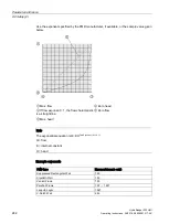
This represents the highest head level supported by the PMD and works in conjunction with
Maximum Flow (2.13.4.3.) (Page 243) to define the highest point in the exponential curve.
Use it when the PMD requires a maximum head and flow reference point. This would include
Exponential, Palmer-Bowlus Flume, H-Flume, and Universal breakpoints.
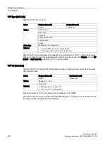
Maximum flow (2.13.4.3.)
Sets the maximum flowrate associated with Maximum Head (2.13.4.2.) (Page 243).
Index
Single-point model
Dual-point model
Global
Transducer
Values
Range: -999 ... 9999
Preset: 1000
Altered by
•
Primary measuring device (2.13.2.) (Page 240)
Related
•
Maximum head (2.13.4.2.) (Page 243)
•
Flow time units (2.13.4.4.) (Page 244)
•
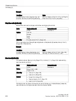
This represents the flow at the highest head level supported by the PMD and works in
conjunction with Maximum Head (2.13.4.2.) (Page 243) to define the highest point in the
exponential curve. Use it when the PMD requires a maximum head and flow reference point.
This would include Exponential, Palmer-Bowlus Flume, H-Flume, and Universal breakpoints.
Also, use this parameter with Flow Time Units (2.13.4.4.) (Page 244) to define the flow rate
units.
Note
•
The display of the measured value is limited to seven characters. A Maximum Flow value
larger than seven characters will not display correctly.
•
If measured value is larger than seven characters, the screen displays ####. A larger unit
[Flow Time Units (2.13.4.4.) (Page 244)] should be used, or number of decimal points
[Flowrate Decimal (2.13.4.6.) (Page 245)] should be reduced.
Содержание HydroRanger 200 HMI
Страница 2: ......
Страница 20: ...Introduction 1 5 Notes on warranty HydroRanger 200 HMI 18 Operating Instructions 06 2018 A5E36281317 AC ...
Страница 24: ...Safety notes HydroRanger 200 HMI 22 Operating Instructions 06 2018 A5E36281317 AC ...
Страница 28: ...Description 3 5 Modbus communication HydroRanger 200 HMI 26 Operating Instructions 06 2018 A5E36281317 AC ...
Страница 159: ...Parameter reference 8 2 Parameter indexing HydroRanger 200 HMI Operating Instructions 06 2018 A5E36281317 AC 157 ...
Страница 276: ...Parameter reference 8 10 Language 6 HydroRanger 200 HMI 274 Operating Instructions 06 2018 A5E36281317 AC ...
Страница 322: ...Pump control reference B 13 Other pump controls HydroRanger 200 HMI 320 Operating Instructions 06 2018 A5E36281317 AC ...
Страница 352: ...Communications C 41 Single parameter access SPA HydroRanger 200 HMI 350 Operating Instructions 06 2018 A5E36281317 AC ...
Страница 354: ...Updating software HydroRanger 200 HMI 352 Operating Instructions 06 2018 A5E36281317 AC ...
Страница 359: ...HydroRanger 200 HMI Operating Instructions 06 2018 A5E36281317 AC 357 Conduit entry for Class I Div 2 applications F ...
Страница 360: ...Conduit entry for Class I Div 2 applications HydroRanger 200 HMI 358 Operating Instructions 06 2018 A5E36281317 AC ...
Страница 361: ...Conduit entry for Class I Div 2 applications HydroRanger 200 HMI Operating Instructions 06 2018 A5E36281317 AC 359 ...
Страница 362: ......
Страница 372: ...Programming chart G 1 Programming chart HydroRanger 200 HMI 370 Operating Instructions 06 2018 A5E36281317 AC ...
Страница 390: ...LCD menu structure H 1 LCD Menu Structure HydroRanger 200 HMI 388 Operating Instructions 06 2018 A5E36281317 AC ...
Страница 403: ......

