Parameter reference
8.6 Setup (2.)
HydroRanger 200 HMI
240
Operating Instructions, 06/2018, A5E36281317-AC
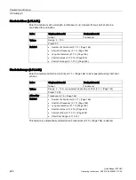
8.6.13.2
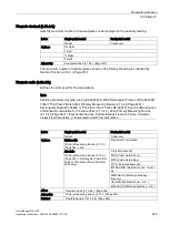
Primary measuring device (2.13.2.)
The type of primary measuring device (PMD) used.
Index
Single-point model
Dual-point model
Global
Transducer
Options
* OFF (no calculation)
Exponential devices [see Flow Exponent (2.13.4.1.) (Page 241)]
Palmer-Bowlus Flume [see PMD Dimensions (2.13.5.) (Page 246)]
H-Flume [see PMD Dimensions (2.13.5.) (Page 246)]
Universal Linear Flow Calculation [see Head 1 (Page 247) and Flow 1 (Page 248)]
Universal Curved Flow Calculation [see Head 1 (Page 247) and Flow 1 (Page 248)]
Rectangular Flume BS-3680 [see PMD Dimensions (2.13.5.) (Page 246)]
Thin Plate V-Notch Weir BS-3680 [see PMD Dimensions (2.13.5.) (Page 246)]
Alters
•
Flow Exponent (2.13.4.1.) (Page 241)
•
PMD Dimensions (2.13.5.) (Page 246)
•
Flowrate Units (2.13.4.7.) (Page 245)
Altered by
Sensor Mode (2.1.3.) (Page 163)
Related
•
Maximum Head (2.13.4.2.) (Page 243)
•
Maximum Flow (2.13.4.3.) (Page 243)
•
Zero Head (2.13.4.5.) (Page 244)
•
Head 1 (2.13.6.1.1.) (Page 247)
•
Flow 1 (2.13.6.1.2.) (Page 248)
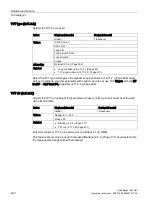
The device is pre-programmed for common PMD flow calculations. If your PMD is not listed,
select the appropriate Universal Flow Calculation.
Associated parameters Maximum Head (2.13.4.2.) (Page 243), Maximum Flow (2.13.4.3.)
(Page 243), and Zero Head (2.13.4.5.) (Page 244) may be scroll accessed. If Sensor Mode
(2.1.3.) (Page 163) = Flow rate in open channel, this value is preset to 1. If Sensor Mode
(2.1.3.) (Page 163) is not set for OCM, it is preset to 0.
8.6.13.3
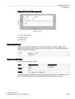
Auto zero head (2.13.3.)
Calibrates Zero Head (2.13.4.5.) (Page 244) based on actual head measurements.
Index
Single-point model
Dual-point model
Global
Transducer
Values
Range: -999 ... 9999
Altered by
Response rate (2.3.4.) (Page 174)
Related
•
Empty (2.2.4.) (Page 170)
•
Offset reading (2.12.6.) (Page 238)
•
Zero head (2.13.4.5.) (Page 244)
•
Содержание HydroRanger 200 HMI
Страница 2: ......
Страница 20: ...Introduction 1 5 Notes on warranty HydroRanger 200 HMI 18 Operating Instructions 06 2018 A5E36281317 AC ...
Страница 24: ...Safety notes HydroRanger 200 HMI 22 Operating Instructions 06 2018 A5E36281317 AC ...
Страница 28: ...Description 3 5 Modbus communication HydroRanger 200 HMI 26 Operating Instructions 06 2018 A5E36281317 AC ...
Страница 159: ...Parameter reference 8 2 Parameter indexing HydroRanger 200 HMI Operating Instructions 06 2018 A5E36281317 AC 157 ...
Страница 276: ...Parameter reference 8 10 Language 6 HydroRanger 200 HMI 274 Operating Instructions 06 2018 A5E36281317 AC ...
Страница 322: ...Pump control reference B 13 Other pump controls HydroRanger 200 HMI 320 Operating Instructions 06 2018 A5E36281317 AC ...
Страница 352: ...Communications C 41 Single parameter access SPA HydroRanger 200 HMI 350 Operating Instructions 06 2018 A5E36281317 AC ...
Страница 354: ...Updating software HydroRanger 200 HMI 352 Operating Instructions 06 2018 A5E36281317 AC ...
Страница 359: ...HydroRanger 200 HMI Operating Instructions 06 2018 A5E36281317 AC 357 Conduit entry for Class I Div 2 applications F ...
Страница 360: ...Conduit entry for Class I Div 2 applications HydroRanger 200 HMI 358 Operating Instructions 06 2018 A5E36281317 AC ...
Страница 361: ...Conduit entry for Class I Div 2 applications HydroRanger 200 HMI Operating Instructions 06 2018 A5E36281317 AC 359 ...
Страница 362: ......
Страница 372: ...Programming chart G 1 Programming chart HydroRanger 200 HMI 370 Operating Instructions 06 2018 A5E36281317 AC ...
Страница 390: ...LCD menu structure H 1 LCD Menu Structure HydroRanger 200 HMI 388 Operating Instructions 06 2018 A5E36281317 AC ...
Страница 403: ......

