


Operating
7.6 mA I/0
HydroRanger 200 HMI
Operating Instructions, 06/2018, A5E36281317-AC
107
7.5.1
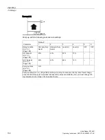
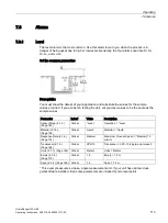
Wiring the discrete inputs
The contacts of the signalling device connected to the discrete inputs may be Normally Open
or Normally Closed.
Example
Normal state for a backup high level switch is open, and the contacts on the discrete input
are wired as normally open. This logic can also be reversed (Normally Open to Normally
Closed or vice versa). Use the Discrete Input Logic (2.9.2.) (Page 209) parameters to set the
state of each discrete input.
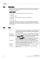
7.5.2
Adjusting the discrete input logic
The default for discrete inputs is Normally Open, which is an Inactive state because no
signal is present on the terminal block connector. It becomes Active only when a signal is
present on the terminal block. To change between Inactive and Active, use Discrete Input
Logic (2.9.2.). (Page 209)
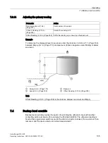
7.6
mA I/0
To integrate the device with other equipment, use the mA input and outputs. The mA input
can be used as a Level measurement or can be passed on to a SCADA system.
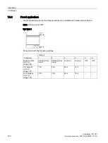
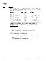
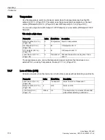
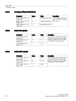
7.6.1
mA Input
Level reading parameters
Parameter
Value
Description
Transducer (2.1.5.) (Page 164)
mA input
Transducer = mA input
mA Input Range (2.6.1.) (Page 184)
*4 to 20 mA
Scale = *4 to 20 mA
0/4 mA Level Value (2.6.2.) (Page 184) 0
4 mA = 0% of span
20 mA Level Value (2.6.3.) (Page 184)
100
20 mA = 100% of span
mA Damp Filter (2.6.4.) (Page 185)
0
Do not damp the input signal
To pass the mA input on to a SCADA system, read the value from the appropriate
communication registers. For more information, see Input/output (R41,070 – R41,143)
(Page 331).
Содержание HydroRanger 200 HMI
Страница 2: ......
Страница 20: ...Introduction 1 5 Notes on warranty HydroRanger 200 HMI 18 Operating Instructions 06 2018 A5E36281317 AC ...
Страница 24: ...Safety notes HydroRanger 200 HMI 22 Operating Instructions 06 2018 A5E36281317 AC ...
Страница 28: ...Description 3 5 Modbus communication HydroRanger 200 HMI 26 Operating Instructions 06 2018 A5E36281317 AC ...
Страница 159: ...Parameter reference 8 2 Parameter indexing HydroRanger 200 HMI Operating Instructions 06 2018 A5E36281317 AC 157 ...
Страница 276: ...Parameter reference 8 10 Language 6 HydroRanger 200 HMI 274 Operating Instructions 06 2018 A5E36281317 AC ...
Страница 322: ...Pump control reference B 13 Other pump controls HydroRanger 200 HMI 320 Operating Instructions 06 2018 A5E36281317 AC ...
Страница 352: ...Communications C 41 Single parameter access SPA HydroRanger 200 HMI 350 Operating Instructions 06 2018 A5E36281317 AC ...
Страница 354: ...Updating software HydroRanger 200 HMI 352 Operating Instructions 06 2018 A5E36281317 AC ...
Страница 359: ...HydroRanger 200 HMI Operating Instructions 06 2018 A5E36281317 AC 357 Conduit entry for Class I Div 2 applications F ...
Страница 360: ...Conduit entry for Class I Div 2 applications HydroRanger 200 HMI 358 Operating Instructions 06 2018 A5E36281317 AC ...
Страница 361: ...Conduit entry for Class I Div 2 applications HydroRanger 200 HMI Operating Instructions 06 2018 A5E36281317 AC 359 ...
Страница 362: ......
Страница 372: ...Programming chart G 1 Programming chart HydroRanger 200 HMI 370 Operating Instructions 06 2018 A5E36281317 AC ...
Страница 390: ...LCD menu structure H 1 LCD Menu Structure HydroRanger 200 HMI 388 Operating Instructions 06 2018 A5E36281317 AC ...
Страница 403: ......