S50A Mobile
Operator’s Manual
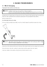
49
DANGER: The tyre changer base MUST BE fIXED to the van in, at least, no.6 POINTS. The 6 fixing points must be
identified by the installer according to each specific van. The cost of the necessary fixing plates is borne
by the customer / installer.
WARNING: The manufacturer is not responsible for the installation and, therefore, for any problem/damage that may
occur if the equipment is not correctly fixed to the van floor.
WITH A SEPARATELY PURCHASED GENERATOR UNIT:
BEFORE CARRYING OUT THE OPERATIONS PREVIOUSLY DESCRIBED IN POINTS 1 TO 8:
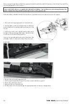
a) Position the generator unit on the tyre changer base and
fix it through 4 M10x 40 screws, by inserting them in the 4
threaded bushings welded to the base (A – B – C – D)
b) Fix the generator unit ignition box to the base, next to the
electrical system board, or at least in an area which allows
to perform switching on and off operations from outside
the van.
c) Electrically connect the ignition box to the tyre changer
electrical board. It is necessary to connect the Pink-Black
cable to the emergency mushroom button of the control
console.
d) Connect the machine plug to the generator three-phase
socket
WARNING: Before installing and using the tyre changer, make sure that drilling the floor does not affect the vehicle
frame integrity. The stability of the vehicle and of the tyre changer inside it may NOT BE ENSURED.
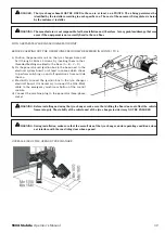
WARNING: During installation, make sure that the overall size of the tyre changer, under operating conditions, does
not interfere with the van sliding door when opened.
OVERALL SIZE OF THE OPENED TYRE CHANGER:
CON IL GRUPPO GENERATORE ACQUISTATO SEPARATAMENTE:
PRIMA DI EFFETTUARE LE OPERAZIONI DA
1
E
8
VISTE PRECEDENTEMENTE
,
BISOGNA
:
a)
Posizionare e fissare il gruppo generatore sul basamento dello smontagomme mediante 4 viti M10x 40, da
applicare sulle 4 boccole filettate saldate sul basamento ( A – B – C – D )
b)
Fissare la scatola di accensione del gruppo
generatore sul basamento, a fianco del quadro
impianto elettrico; o almeno in zona comoda per le
operazioni di accensione e spegnimento quando ci
si trova all’esterno del furgone.
c)
Collegare elettricamente la scatola di accensione al
quadro elettrico dello smontagomme. E’ necessario
collegare il cavo Rosa-Nero al fungo di emergenza
della consolle comandi.
d)
Collegare la spina della macchina alla presa trifase
del generatore
ATTENZIONE Prima di installare e utilizzare lo smontagomme assicurarsi che forando il pianale non si
comprometta l’integrità del telaio del veicolo. Potrebbe NON ESSERE ASSICURATA la stabilità del veicolo
stesso e dello smontagomme posto all’interno.
ATTENZIONE Durante l’installazione assicurarsi che l’ingombro dello smontagomme, in condizioni di
lavoro, non interferisca con la porta scorrevole del furgone quando è aperta.
INGOMBRI DELLO SMONTAGOMME APERTO:
Содержание S50A Mobile
Страница 2: ......
Страница 3: ......
Страница 36: ...36 S50A Mobile Manuale d uso Note...
Страница 37: ...S50A Mobile Manuale d uso 37 Note...
Страница 70: ...70 S50A Mobile Operator s Manual Notes...
Страница 71: ...S50A Mobile Operator s Manual 71 Notes...
Страница 104: ...104 S50A Mobile Manuel d utilisation Notes...
Страница 105: ...S50A Mobile Manuel d utilisation 105 Notes...
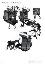
Страница 112: ...112 S50A Mobile Betriebsanleitung 1 4 Positionen der Aufkleber 10 AGT TILT Manuale 1 4 Posizionamento degli adesivi...
Страница 138: ...138 S50A Mobile Betriebsanleitung Anmerkungen...
Страница 139: ...S50A Mobile Betriebsanleitung 139 Anmerkungen...
Страница 146: ...146 S50A Mobile Manual de uso 1 4 Posicionamiento de los adhesivos 10 AGT TILT Manuale 1 4 Posizionamento degli adesivi...
Страница 172: ...172 S50A Mobile Manual de uso Notas...
Страница 173: ...S50A Mobile Manual de uso 173 Notas...


