Tel: 886.2.2175 2930 Email: [email protected]
www.salukitec.com
39
IM distortion. Such distortion products are mostly generated by devices such as amplifiers and mixers in the
system.
The measurement of third-order IM distortion is described below. This section provides an example of how to
display two signals at the same time on the screen of the spectrum analyzer, and introduces how to set the
resolution bandwidth, mixer level and reference level, as well as some marker functions.
2) Measurement procedures
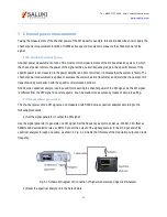
a) Connect the tested instrument with spectrum analyzer as shown in Fig. 4-5.
This example involves one 6dB directional coupler, one 1GHz signal generator and one 1.001GHz signal generator.
Of course, the signal generator of other frequencies are allowed. However, the frequency interval must be
approximately 1MHz in this example.
Spectrum Analyzer
1GHz
1.001GHz
50Ω RF In
Directional
coupler
Signal generator 1
Signal generator 2
Fig. 4-5 Connection of Third-order IM Distortion Measurement System
Set the output frequency of one signal generator as 1GHz and the output frequency of the other signal generator as
1.001GHz, so that the frequency interval of two signals transmitted into the spectrum analyzer is 1MHz.
Set the same output amplitude for both signal generators (-20dBm in this example).
b) Set the spectrum analyzer until both signals are displayed on its screen at the same time.
Press [Reset].
Press [Frequency], [Center Frequency], 1.0005[GHz].
Press [frequency], [Span] and 5[MHz].
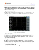
You can see that both signals are at the center of the screen, as shown in Fig. 4-6. If the applied frequency interval
is different from that in this example, select the span more than three times of the frequency interval of the signal
generators.
Содержание S3302A
Страница 1: ...S3302 Series Handheld Spectrum Analyzer Datasheet Saluki Technology Inc...
Страница 70: ...Tel 886 2 2175 2930 Email sales salukitec com www salukitec com 70...
Страница 125: ...Tel 886 2 2175 2930 Email sales salukitec com www salukitec com 125 Fig 7 1 FM Demodulation Analysis Results...
Страница 139: ...Tel 886 2 2175 2930 Email sales salukitec com www salukitec com 139 Fig 8 3 Schematic Diagram of List Scanner...


