Tel: 886.2.2175 2930 Email: [email protected]
www.salukitec.com
47
c) Activate the noise marker.
Press [Maker] and [Noise Marker Off On].
Note: The “Sample” mode of the detector will be enabled automatically. To obtain the noise power under different
bandwidth, you can correct the current bandwidth based on 10×log(BW). For example, if the noise power within 1
kHz bandwidth is to be obtained, 10×log (1000) or 30 dB has to be added to the reading.
d) Reduce the measurement error by increasing the sweep time:
Press [Sweep], [Sweep Time Auto Man] and 3[s].
In the “Average” mode of the detector, you can increase the sweep time so that the trace data are averaged in a
longer interval, so as to reduce the measurement error.
e) Move the marker to 1GHz.
Press [Maker] and rotate the knob on the front panel until the noise marker reading is 1GHz.
The noise marker value is calculated based on 5% of points on the whole sweep trace, with the marker location as
the center. The noise marker will not be at the signal peak since such position has no enough trace points for
calculation. Therefore, when the resolution bandwidth is narrow, the noise level will average trace points below the
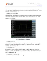
signal peak. As shown in Fig.4-11:
Fig. 4-11 Noise Measurement by Noise Marker Function
f) Set the spectrum analyzer into the zero span mode, with the marker location as the center.
Press [Peak] and [Marker→Center].
Press [frequency], [Span] and [Zero Span].
Read the [Maker].
Содержание S3302A
Страница 1: ...S3302 Series Handheld Spectrum Analyzer Datasheet Saluki Technology Inc...
Страница 70: ...Tel 886 2 2175 2930 Email sales salukitec com www salukitec com 70...
Страница 125: ...Tel 886 2 2175 2930 Email sales salukitec com www salukitec com 125 Fig 7 1 FM Demodulation Analysis Results...
Страница 139: ...Tel 886 2 2175 2930 Email sales salukitec com www salukitec com 139 Fig 8 3 Schematic Diagram of List Scanner...


